
Magnetic resonance imaging devices, methods, and systems for vascular interventions

a magnetic resonance imaging and endovascular technology, applied in the field of endovascular probe localization system, can solve the problems of increasing the range of percutaneous procedures, unsuitable for certain anatomy, and poor use of conventional methods, and achieves the effects of improving the accuracy of endovascular imaging

Pending Publication Date: 2020-04-16
POULIN NATHAN
View PDF4 Cites 0 Cited by
  • Summary
  • Abstract
  • Description
  • Claims
  • Application Information

AI Technical Summary

Benefits of technology

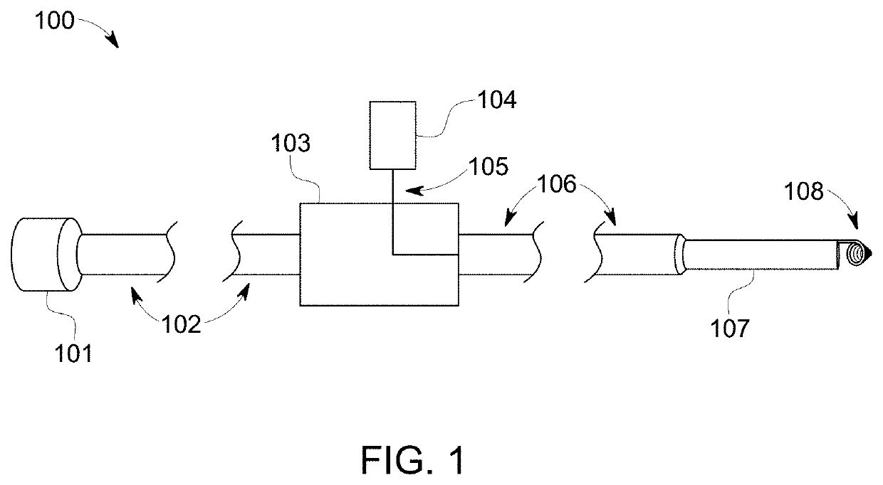
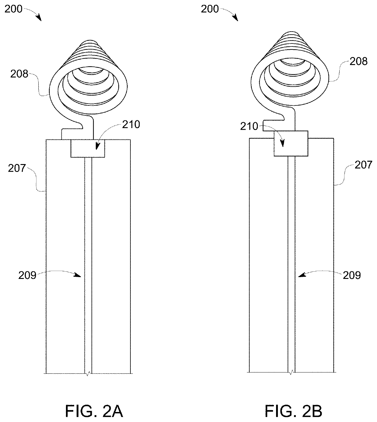
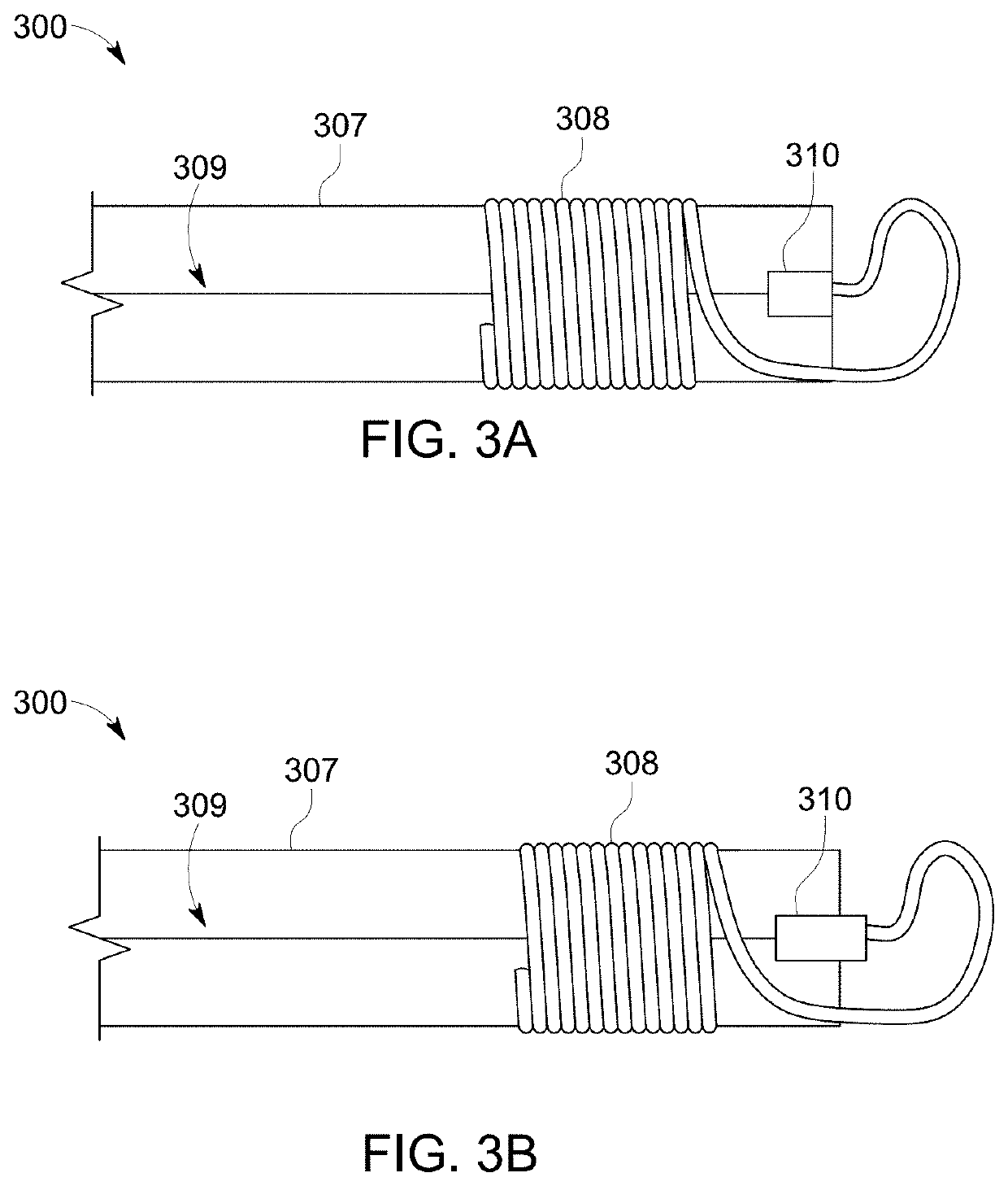
The patent describes a system for tracking the tip of an endovascular probe and collecting images of the surrounding anatomy. The system includes a conductor, a tracking coil with a first end and a second end, and a switchable coupling mechanically coupled to the conductor and the first end of the tracking coil. The switchable coupling can be in a first configuration where the conductor is in electrical contact with the first end of the tracking coil and a second configuration where the conductor is not in electrical contact with the first end of the tracking coil. The switchable coupling can be made of a photoresponsive material or a thermoactive material. The system also includes a light source and an optical fiber in optical communication with the tracking coil. The endovascular probe can be placed in different configurations for different procedures such as tracking, imaging, or ablation. The technical effects of the system include improved accuracy and efficiency in positioning the endovascular probe and collecting relevant images during procedures.

Problems solved by technology

Recently, however, the range of percutaneous procedures has increased, and some procedures currently in use require long fluoro times, which exposes the patient to a continuous dose of ionizing radiation as well as intra-arterial injection of nephrotoxic, iodinated contrast agent.
In addition to these direct safety concerns, X-ray angiograms are mostly restricted to the vessel lumen and the X-ray projections introduce image artifacts.
These conventional methods are not well-suited for certain anatomy.
Deep arteries, such as the coronaries, renal arteries, and peripheral arteries, are poorly seen using external imaging coils.
The field also lacks a probe that seamlessly integrates device tracking, imaging, and ablation without introducing excessive bulk, compromising function, or introducing uncontrollable RF heating hazards.

Method used


Image

  • Magnetic resonance imaging devices, methods, and systems for vascular interventions
  • Magnetic resonance imaging devices, methods, and systems for vascular interventions
  • Magnetic resonance imaging devices, methods, and systems for vascular interventions

Examples


example 1

RF Properties of Exemplary Probe Tip Configurations

[0058]Finite element method (FEM) simulations of one possible ablation loop configuration were conducted, similar to the configuration shown in FIG. 5D. FEM simulation models (COMSOL) were built with a domain with the dielectric properties of blood / saline, to include ‘first order’ physiological sample loading conditions. The switch mechanism was not included in the geometry because only the RF performance of the coil was assessed. The antenna was modeled as the stripped inner conductor of a coaxial transmission line, with an antenna diameter of 2 mm. Only a short segment of the transmission line was included in the simulations (4 mm) with a ground plane situated at the proximal end of the antenna. All conducting components were modeled as perfect electric conductors. The transmission line port was excited with a nominal 1V AC. The port impedance was adjusted to match the antenna impedance and simulations of the reflection (S11) coef...


PUM


Abstract

The present disclosure provides a system for localizing the position of an endovascular probe and collecting high-resolution images of the anatomy surrounding the probe. In particular, a switchable endovascular imaging antenna / probe and related devices are disclosed, which are conveniently switchable between a configuration that allows the localization with high precision of the distal tip of an endovascular probe, and another configuration that allows imaging in the locality of the probe tip. Embodiments are also disclosed capable of delivering ablation therapy.

Description

FIELD OF THE DISCLOSED SUBJECT MATTER[0001]The disclosed subject matter relates to a system for localizing the position of an endovascular probe. In particular, the present disclosed subject matter is directed to a switchable endovascular imaging, radiofrequency probe and related devices, which in one configuration allows the localization with high precision of the distal tip of the endovascular probe, and in another configuration allows imaging in the locality of the probe. In one or more configurations of the disclosed subject matter, ablation therapy may be delivered.DESCRIPTION OF RELATED ART[0002]A variety of methods and systems are known for imaging during interventional procedures. Traditionally, endovascular procedures have relied on X-ray fluoroscopy to guide the navigation of catheters and associated therapeutic devices through vascular routes. Such conventional methods and systems generally have been considered satisfactory for their intended purpose. Recently, however, t...

Claims


Application Information

Patent Timeline
Patent Type & Authority Applications(United States)
IPC IPC(8): A61B5/06A61B18/14A61B5/055
CPCA61B2018/00577A61B18/1492A61B5/055A61B5/062A61B18/18A61B2090/374A61B34/20A61B2034/2051A61B90/37A61B2090/306
Inventor POULIN, NATHAN
Owner POULIN NATHAN
Learn More