Dust barrel capable of carrying out full dust detection in real time, dust collector and full dust detection method

A dust bucket and buzzer technology, which is applied in the installation of vacuum cleaners, electrical equipment, household appliances, etc., can solve problems that affect the working efficiency of vacuum cleaners, secondary pollution, and dust buckets that cannot be real-time

Inactive Publication Date: 2022-05-10
深圳市银舍创新科技有限公司
View PDF6 Cites 0 Cited by
  • Summary
  • Abstract
  • Description
  • Claims
  • Application Information

AI Technical Summary

Problems solved by technology

[0005] The purpose of the present invention is to overcome the deficiencies of the prior art, and provide a dust bucket, a vacuum cleaner and a dust full detection method that can detect full dust in real time, so as to solve the problem that the dust bucket in the vacuum cleaner in the prior art cannot be filled with dust in real time. Detection and timely cleaning, when the dust bucket contains a lot of dust, it will not only affect the working efficiency of the vacuum cleaner, but also prone to technical problems such as dust overflowing from the suction port and causing secondary pollution. Full dust detection and dust full reminder, forcing users to clean the dust bucket in time, improving the working efficiency of the vacuum cleaner and avoiding secondary pollution

Method used


Image

  • Dust barrel capable of carrying out full dust detection in real time, dust collector and full dust detection method

Examples


Embodiment 1

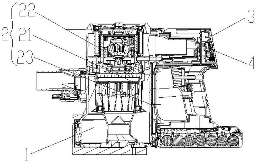
[0024] Embodiment 1 discloses a dust bucket that can detect full dust in real time, such as figure 1 As shown, it includes a dust bucket 1, and also includes a light sensor 2 and a prompt module 3. Specifically, the light sensor 2 is an infrared sensor. The two ends of 21 correspond to the light emitting end 22 and the light receiving end 23. The light transmission channel 21 is a tube body made of thermoplastic polyurethane elastomer material. The inner bending part of the tube body is provided with a reflective film. The light transmission channel 21 The bottom end of the dust bucket 1 is horizontally aligned with the top position of the side wall of the dust bucket 1 and there is a gap between the side wall of the dust bucket 1. The prompt module 3 is arranged outside the dust bucket 1. Specifically, the prompt module 3 is fixedly arranged on the side wall of the vacuum cleaner. On the outer wall of the casing, the light transmitting end 22 and the prompting module 3 are po...

Embodiment 2

[0034]Embodiment 2 discloses a dust bucket that can detect full dust in real time. This embodiment is the same as other structures in Embodiment 1. The difference is that the optical sensor 2 is a laser sensor, and the prompt module 3 is directly fixed on the dust bucket 1. On the outer wall of the outer wall, the light transmission channel 21 is fixedly arranged on the side of the filter end in the inner cavity of the dust bucket 1, and the light emitting end 22 is set correspondingly to the bottom end of the light transmission channel 21, and the light emitting end 22 is fixed on the side of the dust bucket 1 On the wall, the position where the light emitting end 22 is set on the side wall of the dust bucket 1 is connected with the inner cavity of the dust bucket 1, and the light receiving end 23 is set corresponding to the top position of the light transmission channel 21 and the light receiving end 23 is fixedly arranged on the dust bucket 1. On the top wall of the bucket 1...

Embodiment 3

[0036] Embodiment 3 discloses a dust bucket that can detect full dust in real time, including a dust bucket 1, a light sensor 2 and a prompt module 3, specifically, the light sensor 2 is a photoresistive sensor, and the light sensor 2 includes a The light transmission channel 21 on the top of the cavity of the bucket 1 and the light emitting end 22 and the light receiving end 23 are arranged corresponding to the two ends of the light transmission channel 21. The light transmission channel 21 is a tube body made of thermoplastic polyurethane elastomer material. The inner bending part of the body is provided with a reflective film, the bottom end of the light transmission channel 21 is horizontally aligned with the top position of the side wall of the dust bucket 1 and there is a gap between the side wall of the dust bucket 1, and the prompt module 3 is arranged on the dust bucket 1, specifically, the prompting module 3 is fixedly arranged on the outer wall of the vacuum cleaner,...


PUM


Abstract

The invention discloses a dust barrel capable of performing full dust detection in real time, a dust collector and a full dust detection method.The dust barrel comprises the dust barrel, a light sensor and a prompt module, the light sensor comprises a light transmission channel arranged at the top of an inner cavity of the dust barrel, a light emitting end and a light receiving end, and the light emitting end and the light receiving end correspond to the two ends of the light transmission channel in position; the light transmission channel is a pipe body made of a thermoplastic polyurethane elastomer material, a reflective film is arranged at the inner bending position of the pipe body, the bottom end of the light transmission channel is horizontally aligned to the top position of the side wall of the dust barrel, a gap is formed between the bottom end of the light transmission channel and the side wall of the dust barrel, and the prompt module is arranged outside the dust barrel. And the light receiving end is in communication connection with the prompting module. The problems that in the prior art, a dust barrel cannot be subjected to full dust detection in real time and cannot be cleaned in time are solved, the dust barrel full dust detection and dust full prompting can be conducted in real time, a user is forced to clean the dust barrel in time, the working efficiency of the dust collector is improved, and secondary pollution is avoided.

Description

technical field [0001] The invention relates to the technical field of vacuum cleaners, in particular to a dust bucket capable of real-time full dust detection, a vacuum cleaner and a full dust detection method. Background technique [0002] Vacuum cleaners can be divided into vertical, horizontal and portable according to their structure. The working principle of the vacuum cleaner is to use the motor to drive the blades to rotate at high speed, generate air negative pressure in the sealed housing, and absorb dust. [0003] The dust bin in the vacuum cleaner is usually used to collect dust, debris, dust and hair, etc. In the prior art, some dust bins of vacuum cleaners are opaque, and the storage of dust in the dust bin cannot be observed ;Although the dust buckets used by some vacuum cleaners are made of transparent materials, they are often not cleaned in time in actual daily use. Dust overflows from the suction port and causes secondary pollution. [0004] In view of ...

Claims


Application Information

Patent Timeline
Patent Type & Authority Applications(China)
IPC IPC(8): A47L9/28G01V8/14
CPCA47L9/2815G01V8/14
Inventor 李建海赵巍
Owner 深圳市银舍创新科技有限公司
Why Eureka
Try Eureka