Turbine first-stage stationary blade supporting device

A technology of support device and stator, applied in the direction of machine/engine, stator, mechanical equipment, etc., can solve the problem of cumbersome installation process, achieve the effect of improving installation efficiency and reducing the time for axial adjustment

Pending Publication Date: 2022-05-10
CHINA UNITED GAS TURBINE TECH CO LTD
View PDF0 Cites 0 Cited by
  • Summary
  • Abstract
  • Description
  • Claims
  • Application Information

AI Technical Summary

Problems solved by technology

[0005] The main purpose of the present invention is to provide a support device for the first-stage turbine vane, so as to solve the problem of adjusting the axial position of the rotor casing due to the position deviation between the vane and the axial support structure when the gas turbine is assembled in the prior art. The problem of cumbersome installation process
The supporting ring can adjust the axial displacement of the supporting ring relative to the rotor shroud according to the axial position of the fixed end of the stationary blade, so that the supporting ring is in contact with the root of the stationary vane without additional stress on the free end of the stationary vane, realizing It solves the need to adjust the axial position of the entire inner cylinder due to the position deviation between the stator vane and the axial support device during the assembly of the gas turbine, so that the installation process cumbersome questions

Method used


Image

  • Turbine first-stage stationary blade supporting device
  • Turbine first-stage stationary blade supporting device
  • Turbine first-stage stationary blade supporting device

Examples


Embodiment 1

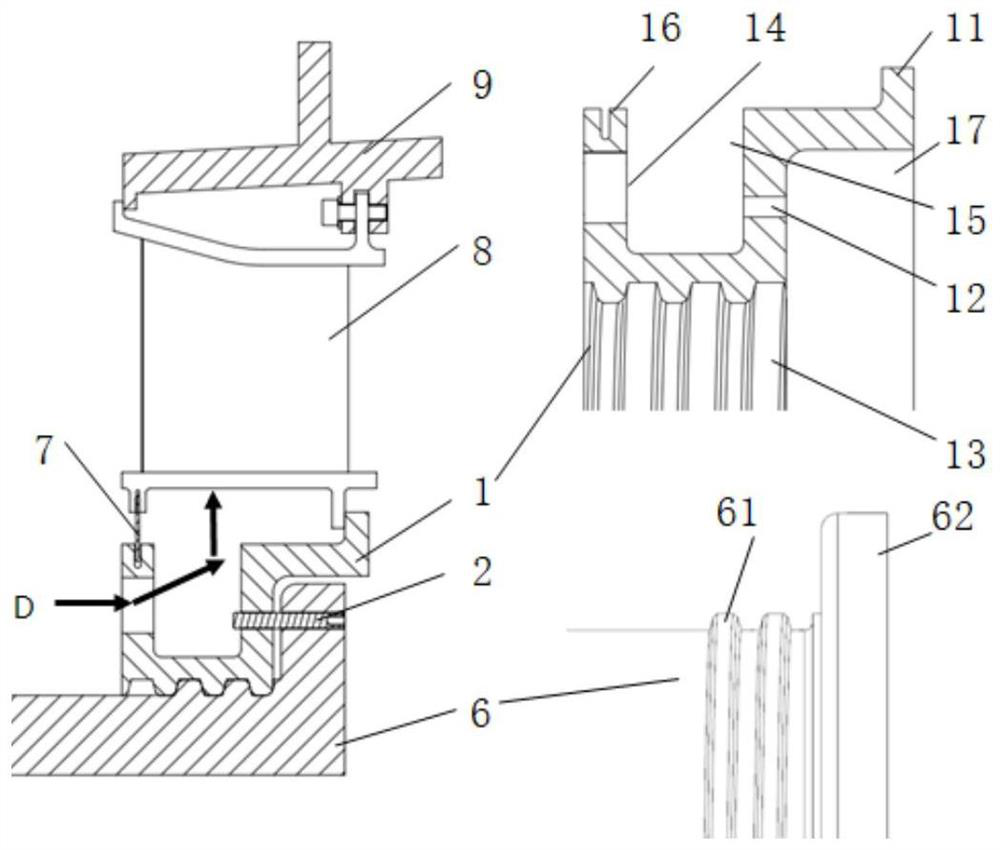
[0055] In Embodiment 1, the first support ring 1 and the first rotor shroud 6 adopt threaded contact instead of the way that the first support ring 1 and the first rotor shroud 6 are completely axially fixed, so that the first rotor shroud 6 does not need The position adjustment process of the first support ring 1 of the stator blade 8 can be realized by moving, which greatly simplifies the installation and positioning process. Moreover, the threaded contact scheme of this embodiment increases the axial position adjustment ability of the first support ring 1 itself, and its position movement depends on the contact rotation of the thread surface, and does not rely on the scheme of grinding the excess of the support ring, and does not require secondary machining. The machining process is simplified, and the rapid adjustment of the axial position of the first support ring 1 is realized.

Embodiment 2

[0056] Embodiment 2 On the basis of Embodiment 1, the adjustment method of the support ring is changed, and the support ring moves linearly relative to the rotor shield to adjust the axial displacement, and the axial quick adjustment of the support device of the stator blade 8 is also realized. The support ring in the second embodiment is the second support ring 20 , and the rotor shield is the second rotor shield 64 .

[0057] Such as Figure 8-Figure 11 As shown, the support device includes the second support ring 20 , the top screw bolt 10 , the first fixing bolt 18 , the second fixing bolt 19 and the second rotor shroud 64 . Figure 10 It shows a plurality of waist-shaped holes arranged in the circumferential direction of the second support ring 20 , and the long side direction of the waist-shaped holes is consistent with the axial direction of the second support ring 20 . The second support ring 20 adjusts the axial displacement of the second support ring 20 relative to ...


PUM


Abstract

The invention discloses a turbine first-stage stationary blade supporting device of a gas turbine, a stationary blade (8) is provided with a fixed end and a free end, the supporting device supports the free end of the stationary blade (8), the supporting device comprises a supporting ring (1, 20) and a rotor protective cover (6, 64), the rotor protective cover (6, 64) carries the supporting ring (1, 20), and in the axial direction of the rotor protective cover (6, 64), according to the axial position of the fixed end of the stationary blade (8), the supporting ring (1, 20) and the rotor protective cover (6, 64) can be separated from each other. The axial displacement of the support ring (1, 20) relative to the rotor shroud (6, 64) is adjusted. The axial displacement of the supporting ring relative to the rotor shield can be adjusted according to the axial position of the fixed end of the stationary blade, so that the supporting ring is in contact with the blade root of the stationary blade, the free end of the stationary blade cannot bear extra stress, and rapid adjustment of the axial supporting device of the turbine first-stage stationary blade during cold-state installation is achieved.

Description

technical field [0001] The invention relates to a heavy-duty gas turbine, in particular to a support device for a first-stage stationary blade of a heavy-duty gas turbine. Background technique [0002] During the operation of the gas turbine, the first-stage stator blades of the turbine are impacted by the high-temperature and high-speed airflow from the outlet of the combustion chamber, and the axial position of the stator blades needs to be constrained. For the suspended first-stage turbine vane, its radial outer side is connected with the turbine holding ring without axial movement margin, and its radial inner side is a relatively free end without rigid constraints, and is usually supported axially by a support ring The root of the stationary blade prevents the blade from being damaged due to large-angle rotation under the action of aerodynamic force, and also reduces the leakage of cooling airflow. However, the turbine's first-stage vanes are mounted on the turbine reta...

Claims


Application Information

Patent Timeline
IPC IPC(8): F01D9/04
CPCF01D9/042
Inventor 朱卫东李志伟
Owner CHINA UNITED GAS TURBINE TECH CO LTD
Why Eureka
Try Eureka