LED radar speed measurement screen and installation structure thereof
A radar speed measurement and installation structure technology, which is applied in the direction of measuring devices, identification devices, workpiece clamping devices, etc., can solve the problems of inconvenient assembly and loading, inconvenient anti-blocking automatic cleaning, etc., and achieve the effect of avoiding inconvenient use and facilitating automatic cleaning
- Summary
- Abstract
- Description
- Claims
- Application Information
AI Technical Summary
Problems solved by technology
Method used
Image
Examples
Embodiment 1
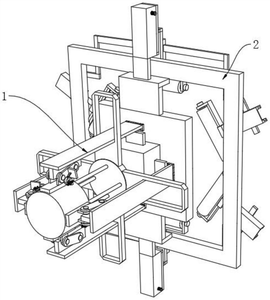
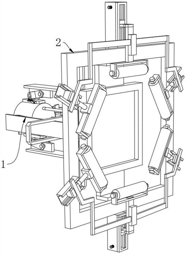
[0033] see Figure 7-9 , an LED radar speed measuring screen, comprising a self-cleaning protection speed measuring screen structure 2, the self-cleaning protection speed measuring screen structure 2 includes a speed measuring screen main body 33, a first fitting bracket 34, a protective light-transmitting plate 35 and a self-cleaning module 36, the speed measuring screen The top and the bottom of the main body 33 are fixedly connected with a first fitting bracket 34, one end of the first fitting bracket 34 is fixedly connected with a protective light-transmitting plate 35, and the top and bottom of the protective light-transmitting plate 35 are fixedly connected with an automatic Cleaning module 36.
[0034] The self-cleaning module 36 includes an active cleaning module and a driven cleaning module, and one end of the active cleaning module is provided with a driven cleaning module;
[0035] The active cleaning module includes a built-in carrying case 37, a second motor 38, ...
Embodiment 2
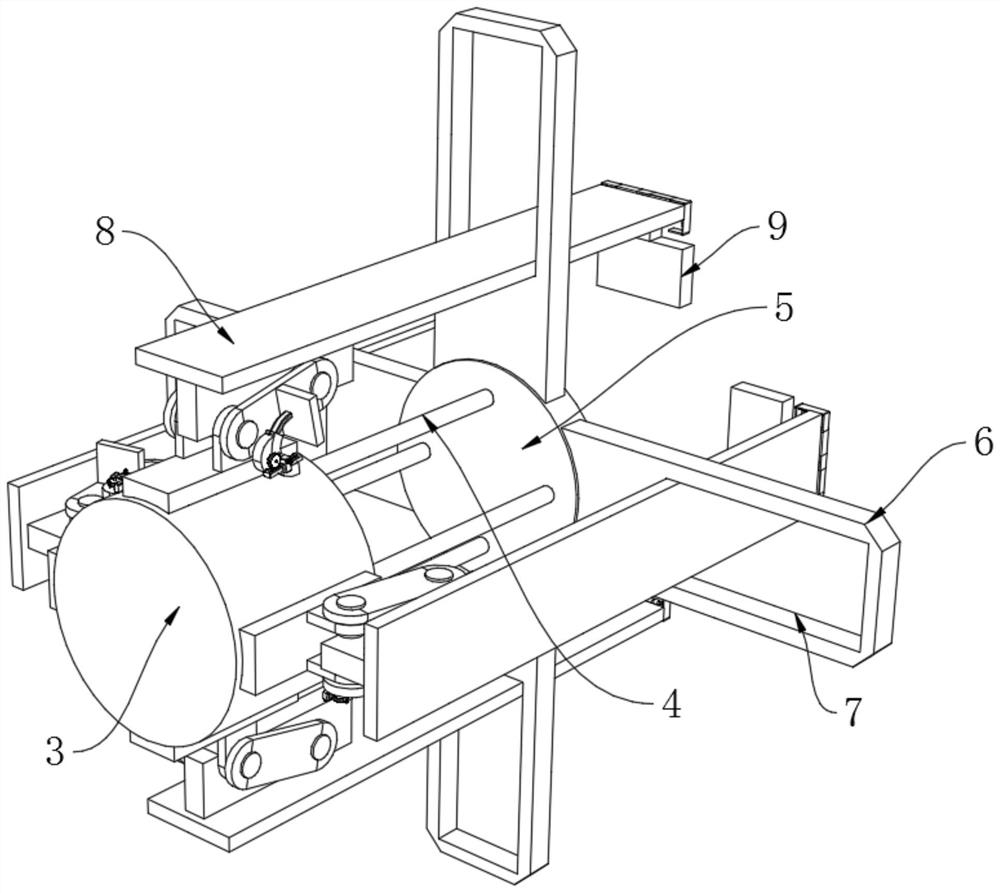
[0040] see Figure 1-6 , an installation structure of an LED radar speed measuring screen, which is used for any one of a kind of LED radar speed measuring screen in the above-mentioned embodiment, including a stable installation structure 1, and the stable installation structure 1 includes a first matching column 3, a light rod 4, The second mounting column 5, the extension guide plate 6, the auxiliary limit groove 7, the clamping motion guide module 8 and the stabilizing claw module 9, the four ends of the first mounting column 3 are welded with polished rods 4, and the polished rods 4 The end far away from the first mounting column 3 is welded with a second mounting column 5, and the four ends of the second mounting column 5 are welded with an extension guide plate 6, and the inner side of the extension guide plate 6 is provided with an auxiliary limit The slot 7 and the four ends of the first mounting column 3 are fixedly connected with a clamping motion guide module 8 , a...
PUM
 Abstract
Description
Claims
Application Information
 - R&D
- Intellectual Property
- Life Sciences
- Materials
- Tech Scout
- Unparalleled Data Quality
- Higher Quality Content
- 60% Fewer Hallucinations
Browse by: Latest US Patents, China's latest patents, Technical Efficacy Thesaurus, Application Domain, Technology Topic, Popular Technical Reports.
© 2025 PatSnap. All rights reserved.Legal|Privacy policy|Modern Slavery Act Transparency Statement|Sitemap|About US| Contact US: help@patsnap.com


