Feeding device for soil remediation agent
A technology of soil remediation agent and putting device is applied in the field of soil remediation, which can solve the problems of uniform distribution, short life, loss of water storage function, etc., and achieve the effects of long-term water storage, avoiding water loss and reducing labor.
- Summary
- Abstract
- Description
- Claims
- Application Information
AI Technical Summary
Problems solved by technology
Method used
Image

Examples
Example Embodiment
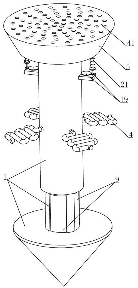
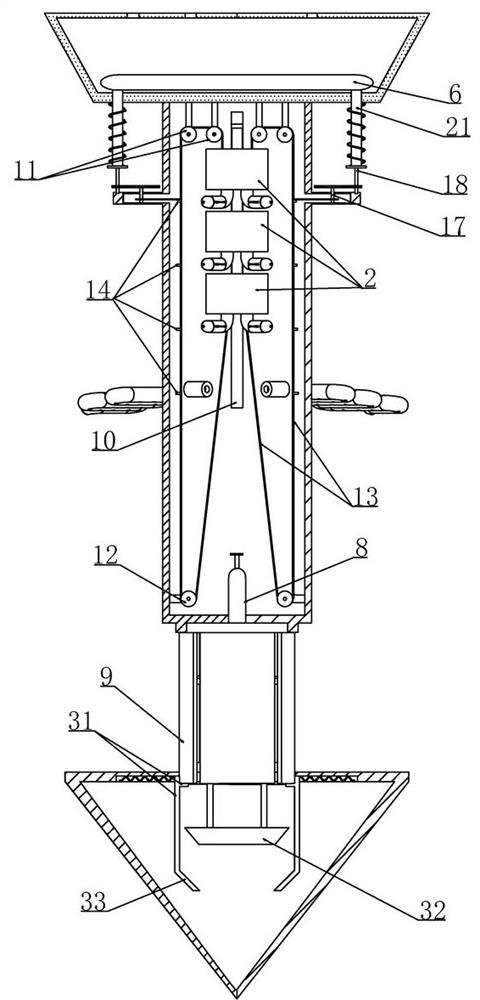
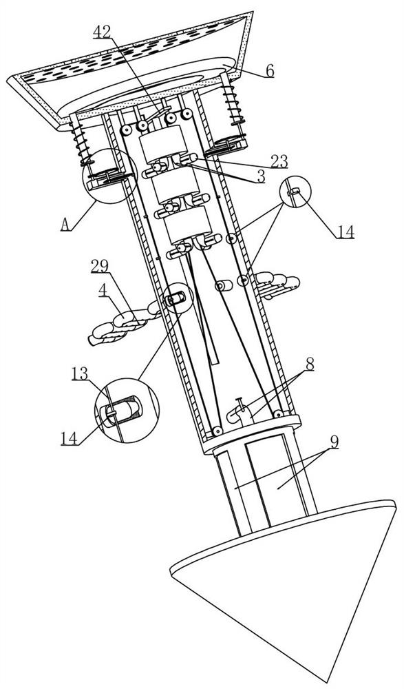
[0029] Embodiment 1, this embodiment provides a kind of dispensing device for soil remediation agent, as attached figure 1 As shown, the cylinder 1 is included and the cylinder 1 is used to be pre-embedded in the soil. The improvement of this program is: as attached figure 2 As shown, a number of fixedly installed liquid storage cylinders 2 are arranged at vertical intervals in the cylinder 1, as shown in the attached image 3 As shown, a slide rod 42 is fixed on the uppermost liquid storage cylinder 2 and several fixedly installed liquid storage cylinders 2 are vertically slid and installed on the inner wall of the cylinder 1 through the slide rod 42, as shown in the attached Image 6 As shown, there is a liquid outlet pipe 3 at the bottom of the liquid storage cylinder 2 and a control valve is provided on the liquid outlet pipe 3 (the liquid storage cylinder 2 stores a liquid water retention agent). image 3 As shown, a permeation tube 4 is provided on the outer wall of th...
Example Embodiment
[0037] Embodiment 2, on the basis of embodiment 1, as attached figure 2 As shown, the transmission mechanism includes wire wheel sets arranged in the cylinder 1 and located on both axial sides of several liquid storage cylinders 2 respectively. 1 The lower part is rotatably installed with a lower wire pulley 12 and is connected to a wire rope 13 on one side of the top wall of the uppermost liquid storage cylinder 2 (the other side of the liquid storage cylinder 2 is also connected to a wire rope 13, which is symmetrically arranged on both sides), and the wire rope 13 After being guided by the two upper wire wheels 11 and the lower wire wheel 12, it is connected to the bottom wall of the lowermost liquid storage cylinder 2;
[0038] as attached figure 2 As shown, on the wire rope 13 in the vertical stage, a number of semicircular plates 14 that cooperate with the control mechanism are vertically spaced (and the diameter of the semicircular plates 14 increases successively fr...
Example Embodiment
[0042] Embodiment 3, on the basis of embodiment 2, as attached Figure 4 As shown, the control mechanism includes two blocking rods 15 arranged at intervals and slidably installed on the cylinder 1. The two blocking plates are respectively located on both sides of the wire rope 13 and the lower end surfaces of the blocking rods 15 are in contact with the semicircular plate 14 (at this time, the two blocking rods 15 is less than the diameter of the semicircular plate 14, so that the semicircular plate 14 installed on the wire rope 13 cannot cross the two blocking rods 15, and then the wire rope 13 cannot move), and the ends of the two blocking rods 15 away from the wire rope 13 are respectively provided with The gear train (not numbered in the figure), and the two gear trains mesh together with the transmission gear 16 that is rotatably installed on the cylinder 1. When the transmission gear 16 rotates, it can synchronously drive the two blocking rods 15 to move toward or away f...
PUM
 Abstract
Description
Claims
Application Information
 - R&D Engineer
- R&D Manager
- IP Professional
- Industry Leading Data Capabilities
- Powerful AI technology
- Patent DNA Extraction
Browse by: Latest US Patents, China's latest patents, Technical Efficacy Thesaurus, Application Domain, Technology Topic.
© 2024 PatSnap. All rights reserved.Legal|Privacy policy|Modern Slavery Act Transparency Statement|Sitemap