
Femoral porous intramedullary nail combined auxiliary steel plate double cortical screw internal fixation system

An intramedullary nail and screw technology, applied in the field of femoral porous intramedullary nail and its fixation system, can solve the problems of nonunion, internal fixation failure, affecting fracture healing, etc., and achieve the effect of improving the quality of life

Inactive Publication Date: 2022-05-13
南通市中医院
View PDF0 Cites 0 Cited by
  • Summary
  • Abstract
  • Description
  • Claims
  • Application Information

AI Technical Summary

Problems solved by technology

Once the above-mentioned complications occur, doctors often use auxiliary plates for fixation on the basis of retaining the original intramedullary nails. However, due to the existence of intramedullary nails, this auxiliary plate can only achieve single cortical screw fixation with auxiliary plates in the past.
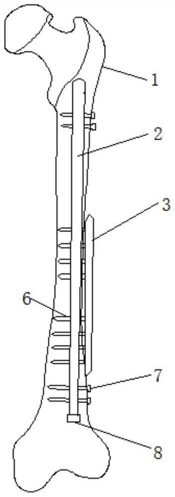
Currently, if image 3 As shown, the common femoral intramedullary nail has only 5 interlocking screw holes at the distal end and 2 proximal interlocking screw holes. It is used for interlocking fixation of comminuted fractures at the distal end of the fracture. For non-isthmic fractures of the femoral shaft, due to the wide medullary cavity, only relying on interlocking screws at the distal and proximal parts for fixation, the fracture still has a certain degree of lateral Towards moving and rotating stress, affecting fracture healing, resulting in nonunion, internal fixation failure and other complications

Method used


Image

  • Femoral porous intramedullary nail combined auxiliary steel plate double cortical screw internal fixation system
  • Femoral porous intramedullary nail combined auxiliary steel plate double cortical screw internal fixation system
  • Femoral porous intramedullary nail combined auxiliary steel plate double cortical screw internal fixation system

Examples


Embodiment Construction

[0012] In order to make the technical problems, technical solutions and advantages to be solved by the present invention clearer, the following will describe in detail with reference to the drawings and specific embodiments.

[0013] In the description of the present invention, it should be noted that the terms "center", "upper", "lower", "left", "right", "vertical", "horizontal", "inner", "outer", " The orientation or positional relationship indicated by "front", "rear", etc. is based on the orientation or positional relationship shown in the drawings, which is only for the convenience of describing the present invention and simplifying the description, rather than indicating or implying that the referred device or element must have a specific orientation, are constructed and operate in a particular orientation and therefore are not to be construed as limiting the invention. In addition, the terms "first", "second", and "third" are used for descriptive purposes only, and shou...


PUM


Abstract

The invention discloses a thighbone porous intramedullary nail combined locking bone fracture plate double cortical bone screw internal fixation system, which is characterized by comprising a porous intramedullary nail, a tail cap, a far-end lock nail, a near-end lock nail, a locking bone fracture plate and a plurality of cortical bone screws, and provides intramedullary combined extramedullary firm fixation; a plurality of thread self-locking screw holes are formed in the locking bone fracture plate; the intramedullary nail is provided with a tail cap, a locking nail, a far-end interlocking locking hole and a near-end interlocking locking hole which are owned by a common femoral intramedullary nail. A plurality of screw holes are additionally formed in the middle cylinder part of the intramedullary nail, the positions (intervals) of the screw holes are matched with the positions (intervals) of inherent screw holes of the locking bone fracture plate, the cortical bone screws penetrate through the screw holes in the middle cylinder part of the intramedullary nail, and locking and fixing of the double cortical bone screws of the locking bone fracture plate combined with the intramedullary nail are achieved. Lateral movement and shear stress of the fracture broken end can be effectively controlled, axial, bending and rotating stability of the fracture broken end is maintained, and early movement and early load bearing can be achieved after fixation.

Description

technical field [0001] The invention belongs to the technical field of medical auxiliary treatment equipment, and in particular relates to a femoral porous intramedullary nail and a fixing system thereof. Background technique [0002] For non-isthmus fractures of the femoral shaft, due to the wide medullary cavity, there is still a certain amount of lateral movement and rotational stress at the fracture end due to the wide medullary cavity, and there is still a certain amount of lateral movement and rotational stress at the fracture end, which affects fracture healing, and complications such as nonunion and internal fixation failure often occur. occur. Once the above-mentioned complications occur, doctors often add auxiliary plate fixation on the basis of retaining the original intramedullary nail. However, due to the existence of the intramedullary nail, this auxiliary plate can only achieve single cortical screw fixation with the auxiliary plate in the past. Currently, if...

Claims


Application Information

Patent Timeline
Patent Type & Authority Applications(China)
IPC IPC(8): A61B17/74A61B17/72A61B17/80
CPCA61B17/744A61B17/80
Inventor 姜江周轶顾伏龙
Owner 南通市中医院
Learn More