Magneto-rheological shock absorber
A magneto-rheological shock absorber and magneto-rheological fluid technology, applied in shock absorbers, springs/shock absorbers, shock absorbers, etc., can solve problems such as inability to apply impact loads and inability to alleviate impact loads
Pending Publication Date: 2022-05-13
ZHUZHOU TIMES NEW MATERIALS TECH
0 Cites 0 Cited by
AI-Extracted Technical Summary
Problems solved by technology
However, the magneto-rheological shock absorber in the prior art cannot be applied to diff...
Method used
In one embodiment of the present invention, the inside of the first side end surface of the cylinder block 10 and the inside of the second side end surface are all provided with the sealing ring 70 that the piston rod 21 forms a seal, thereby effectively ensuring that the first chamber 12 and the sealing effect in the second chamber 13.
[0023] FIG. 2 is a schematic structural view of the flow member 30 in the magneto-rheological shock absorber 100 according to the present invention. According to the present invention, as shown in FIG. 2 , the flow-through member 30 is configured as a hollow sleeve, and includes a groove 31 disposed on the outer periphery in the circumferential direction, and a magnetic field generator 32 is disposed inside the groove 31 . According to the present invention, the magnetic field generator 32 can generate a magnetic field and act on the magnetorheological fluid, thereby changing the state of the magnetorheological fluid, so that the magnetorheological shock absorber 100 can adjust the damping force more easily. In a specific embodiment, the magnetic field generator 32 is an electromagnet.
[0027] Fig. 3 is a cross-sectional view of the A-A plane in Fig. 2. In one embodiment of the present invention, as shown in FIG. 3 , the second flow channel 33 is provided with several sections and all of them are on the same circumferential line. In this way, the magnetorheological fluid flows from the first chamber 12 into the second chamber 13 more easily through the second flow channel 33 . In addition, any adjacent two segments of the second channel 33 are separated. In this way, the flow rate of the magnetorheological fluid passing through the second flow channel 33 in the chamber 11 is easier to control.
[0028] According to the present invention, as shown in FIG. 2, the piston unit 20 includes a one-way control valve 60. The one-way control v...
Abstract
The invention belongs to the field of shock absorbers, and particularly discloses a magnetorheological shock absorber. The magnetorheological fluid is contained in the cylinder body, and the piston unit is arranged in the cylinder body. The piston unit comprises a piston rod and a circulation piece arranged on the piston rod in a sleeving mode. The first connecting part of the piston rod horizontally extends outwards from the first side end face of the cylinder body. The shock absorber further comprises a connector fixedly connected with the first connecting part of the piston rod. The circulation piece comprises a magnetic field generator, and the magnetic field generator can generate a magnetic field acting on the magnetorheological fluid. The damping force can be intelligently adjusted.
Application Domain
SpringsNon-rotating vibration suppression +1
Technology Topic
PhysicsMagneto +5
Image
Examples
- Experimental program(1)
Example Embodiment
[0019] The present invention will be further described below in conjunction with accompanying drawing.
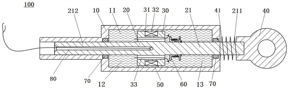
[0020] figure 1 The structure of the magneto-rheological shock absorber 100 according to the present invention is schematically shown. like figure 1 As shown, the magneto-rheological shock absorber 100 according to the present invention includes a cylinder 10 and a piston unit 20 . Therein, the cylinder body 10 is configured as a hollow sleeve, and a chamber 11 is formed in the cylinder body 10 . Chamber 11 is used to accommodate magnetorheological fluid (not shown). The piston unit 20 is disposed within the chamber 11 of the cylinder 10 and is capable of reciprocating movement within the chamber 11 of the cylinder 10 . Magneto-rheological fluid (MRF) is a new type of intelligent liquid material, which is mainly composed of non-magnetic liquid and high magnetic permeability and low hysteresis micro-magnetic particles uniformly dispersed in it. Under the action of a magnetic field, this material can instantly change from a Newtonian fluid with good fluidity to a semi-solid, and the change is continuous, controllable and reversible. Magnetorheological fluids and their properties are well known to those skilled in the art.
[0021] According to the present invention, if figure 1 As shown, the piston unit 20 comprises a piston rod 21 and a flow element 30 . Wherein, the flow element 30 is sheathed on the piston rod 21 , so as to divide the chamber 11 into a first chamber 12 and a second chamber 13 located on two sides. The piston rod 21 is configured as a rod-shaped structure, and the piston rod 21 can reciprocate in the chamber 11 . The piston rod 21 includes a first connecting portion 211 penetrating through the first chamber 12 and a second connecting portion 212 penetrating through the second chamber 13 , respectively. Wherein, the first connecting portion 211 passes through the first chamber 12 and horizontally extends outward from the first side end surface of the cylinder body 10 . The second connecting portion 212 passes through the second chamber 13 and extends horizontally outward from the second side end surface of the cylinder 10 .
[0022] According to the present invention, if figure 1 As shown, the magnetorheological shock absorber 100 includes a connector 40 . The connecting head 40 is connected to the end of the first connecting portion 211 of the piston rod 21 , so that the connecting head 40 is installed outside the cylinder body 10 . In addition, a second spring 41 is disposed between the connecting head 40 and the cylinder body 10 , and the second spring 41 is sleeved on the piston rod 21 to support the reciprocating movement of the piston rod 21 in the axial direction.
[0023] figure 2 It is a schematic structural diagram of the flow element 30 in the magneto-rheological shock absorber 100 according to the present invention. According to the present invention, if figure 2 As shown, the flow-through member 30 is configured as a hollow sleeve, and includes a groove 31 disposed on the outer circumference in the circumferential direction, and a magnetic field generator 32 is disposed inside the groove 31 . According to the present invention, the magnetic field generator 32 can generate a magnetic field and act on the magnetorheological fluid, thereby changing the state of the magnetorheological fluid, so that the magnetorheological shock absorber 100 can adjust the damping force more easily. In a specific embodiment, the magnetic field generator 32 is an electromagnet.
[0024] In one embodiment of the present invention, the outer diameter of the flow element 30 is smaller than the inner diameter of the cylinder body 10 , so that an annular first flow channel 50 is formed between the flow element 30 and the cylinder body 10 . The first flow channel 50 provides a stable flow channel for the first chamber 12 and the second chamber 13 .
[0025] According to the present invention, the magneto-rheological shock absorber 100 includes a compression process and a reset process. During the compression process, the magnetic field generator 32 generates a magnetic field to make the piston unit 20 gradually compress the space in the first chamber 12 , and the piston rod 21 overcomes the force of the second spring 41 and moves toward the first chamber 12 . Thus, part of the magnetorheological fluid in the first chamber 12 flows into the second chamber 13 through the first channel 50 . During the resetting process, the magnetic field generator 32 generates a magnetic field to make the piston unit 20 gradually compress the space in the second chamber 13 . Thus, all the magnetorheological fluid in the second chamber 13 flows to the first chamber 12 through the first channel 50 .
[0026] According to the invention, the flow element 30 comprises a second flow channel 33 . The second flow channel 33 runs through the interior of the flow element 30 and can guide the magnetorheological fluid from the first chamber 12 to the second chamber 13 . During the above-mentioned compression process, the magnetorheological fluid actually has two different flow channels, one of which is that the magnetorheological fluid flows from the first chamber 12 through the first flow channel 50 into the second chamber 13, The other is that the magnetorheological fluid flows from the first chamber 12 into the second chamber 13 through the second channel 33 . In this way, the flow area of the magnetorheological fluid is large during the compression process, and the damping force generated is small, thereby effectively reducing the buffer force; the flow area of the fluid is small during the reset process, and the damping force generated is small. The force is large, thereby effectively dissipating the impact energy. Its role is described below.
[0027] image 3 for figure 2 A cross-sectional view of plane A-A in the center. In one embodiment of the present invention, as image 3 As shown, the second flow channel 33 is provided with several sections and all of them are on the same circumferential line. In this way, the magnetorheological fluid flows from the first chamber 12 into the second chamber 13 more easily through the second flow channel 33 . In addition, any adjacent two segments of the second channel 33 are separated. In this way, the flow rate of the magnetorheological fluid passing through the second flow channel 33 in the chamber 11 is easier to control.
[0028] According to the present invention, if figure 2 As shown, the piston unit 20 includes a one-way control valve 60 . The one-way control valve 60 is disposed in the second chamber 13 of the cylinder body 10 and sleeved on the first connecting portion 211 of the piston rod 21 . In addition, one end of the one-way control valve 60 is in contact with the flow element 30 , and the outer diameter of the one-way control valve 60 is larger than the outer diameter of the second channel 33 in the flow element 30 . In this way, the one-way control valve 60 can effectively control the opening and closing of the second flow channel 33 more easily.
[0029] According to the present invention, if figure 2 As shown, the one-way control valve 60 includes a pressure plate 61 , a first spring 62 , and a baffle 63 . Wherein, the baffle plate 63 is fixedly installed on the piston rod 21 and is used to limit the movement range of the pressing plate 61 and the first spring 62 . One end of the first spring 62 is fixedly connected to the baffle 63 , so that the first spring 62 is indirectly fixed on the piston rod 21 through the baffle 63 ; the other end of the first spring 62 is fixedly connected to the pressure plate 61 . The bottom of the pressing plate 61 is connected with the piston rod 21 and can move axially on the piston rod 21 . Specifically, the pressing plate 61 can reciprocate axially on the piston rod 21 in combination with the first spring 62 , so as to control the opening and closing of the second channel 33 .
[0030]In an embodiment of the present invention, the pressing plate 61 abuts against the second flow channel 33 , and the outer diameter of the pressing plate 61 is larger than the outer diameter of the second flow channel 33 . In this way, the one-way control valve 60 can effectively control the opening and closing of the second flow passage 33 through the pressing plate 61 . That is to say, during the compression process, the magnetorheological fluid in the first chamber 12 flows toward the direction of the second chamber 13 . Since the magneto-rheological fluid in the first chamber 12 pushes the pressure plate 61 through the second flow channel 33, the pressure plate 61 moves away from the flow member 30 under the action of the magneto-rheological fluid against the force of the first spring 62 , so as to open the outlet of the second flow channel 33 so that the magnetorheological fluid in the first chamber 12 flows to the second chamber 13 through the second flow channel 33 . In addition, the magnetorheological fluid in the first chamber 12 can also flow to the second chamber 13 through the first channel 50 . During the reset process, the magnetorheological fluid in the second chamber 13 moves toward the direction of the first chamber 12 . Since the magnetorheological fluid in the second chamber 13 exerts pressure on the pressing plate 61 , the pressing plate 61 closes the outlet of the second flow channel 33 under the action of the magnetorheological fluid. At this time, the magnetorheological fluid can only flow from the second chamber 13 to the first chamber 12 through the first channel 50 .
[0031] According to an embodiment of the present invention, during the above-mentioned compression process, the piston unit 20 simultaneously opens the two magnetorheological fluid flow channels, the first flow channel 50 and the second flow channel 33, so that by increasing the A larger flow area makes the flow of the magneto-rheological fluid more smooth, allowing the magnetorheological shock absorber 100 to have a smaller damping force, thereby effectively reducing the buffering force. During the reset process as described above, the piston unit 20 only opens the first flow channel 50, a magneto-rheological fluid flow channel, so that by reducing the flow area of the magnetorheological fluid, the flow speed of the magnetorheological fluid is slowed down, allowing the magneto-rheological fluid to The variable shock absorber 100 has greater damping force, thereby effectively dissipating impact energy.
[0032] In one embodiment of the present invention, an iron core 80 is also arranged in the piston rod 21 (in figure 1 shown in ), and through wire 81 (in figure 2 shown in ) communicates with the magnetic field generator 32, thereby controlling the state of the magnetorheological fluid in the first chamber 12 and the second chamber 13.
[0033] In one embodiment of the present invention, both the inside of the first side end surface and the inside of the second side end surface of the cylinder body 10 are provided with a sealing ring 70 formed by the piston rod 21 to seal, thereby effectively ensuring that the first chamber 12 and the second chamber are sealed. The sealing effect in the second chamber 13.
[0034] In the present invention, the one-way control valve 60 enables the piston unit 20 to form different magneto-rheological fluid flow channels in the process of compression and reset, thereby realizing intelligent adjustment of the damping force. In addition, the present invention utilizes the properties of the magneto-rheological fluid to assist in adjusting the damping force through the control of the magnetic field generator 32 .
[0035] The above are only preferred embodiments of the present invention, but the protection scope of the present invention is not limited thereto. Those skilled in the art can easily make changes or changes within the disclosed scope of the present invention, and such changes or changes should be covered within the protection scope of the present invention. Therefore, the protection scope of the present invention should be determined by the protection scope of the claims.
PUM


Description & Claims & Application Information
We can also present the details of the Description, Claims and Application information to help users get a comprehensive understanding of the technical details of the patent, such as background art, summary of invention, brief description of drawings, description of embodiments, and other original content. On the other hand, users can also determine the specific scope of protection of the technology through the list of claims; as well as understand the changes in the life cycle of the technology with the presentation of the patent timeline. Login to view more.