A detection device for a motorcycle clutch

A detection device and clutch technology are applied in the field of clutch detection, which can solve the problems of difficult positioning, inability to enter the casing, and unfavorable detection of screw holes of the clutch protective casing, and achieve the effect of simple operation and convenient observation.

Active Publication Date: 2022-06-17
JINAN HONGZHENG TECH
View PDF9 Cites 0 Cited by
  • Summary
  • Abstract
  • Description
  • Claims
  • Application Information

AI Technical Summary

Problems solved by technology

[0003] However, at present, it is necessary to detect the position of the screw hole of the clutch protective shell after the production of the clutch protective shell is completed. During the detection, the clutch protective shell is clamped by a clamp, and the produced shell is checked by the detection pin corresponding to the screw hole of the standard shell. Detection, when a screw hole position is unqualified, all detection pins cannot enter the corresponding screw holes on the shell, and the detection pins are not equipped with a mechanism for marking the unqualified screw holes on the clutch protective case, it is difficult for the detection personnel Quickly observe the unqualified screw holes; and when the clutch protective shell is detected and placed, one of the screw holes needs to correspond to the detection pin, which is difficult to quickly locate and is not conducive to the detection of the clutch protective shell screw holes

Method used


Image

  • A detection device for a motorcycle clutch
  • A detection device for a motorcycle clutch
  • A detection device for a motorcycle clutch

Examples


Embodiment Construction

[0028] In order to make it easy to understand the technical means, creation features, achieved goals and effects of the present invention, the present invention will be further described below with reference to the specific embodiments.

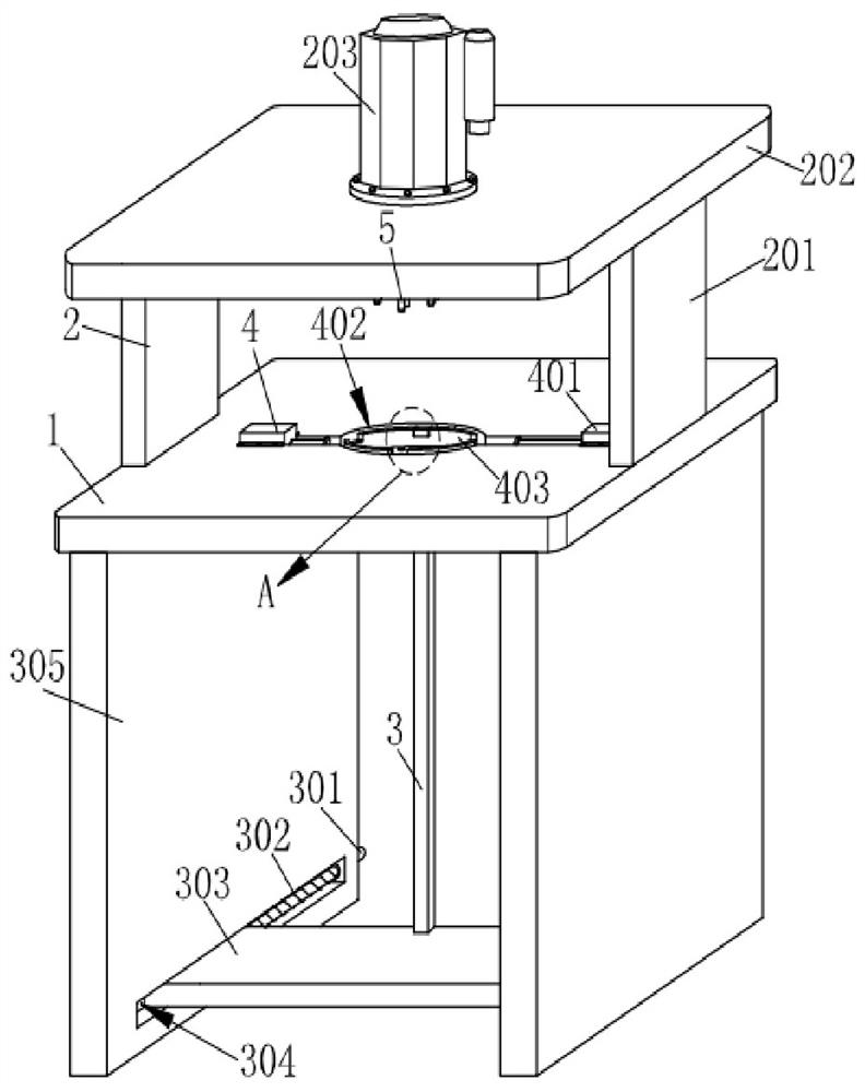
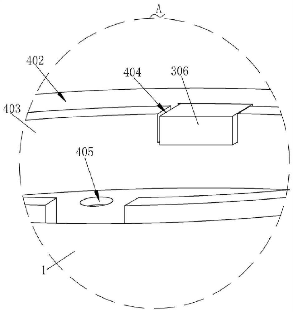
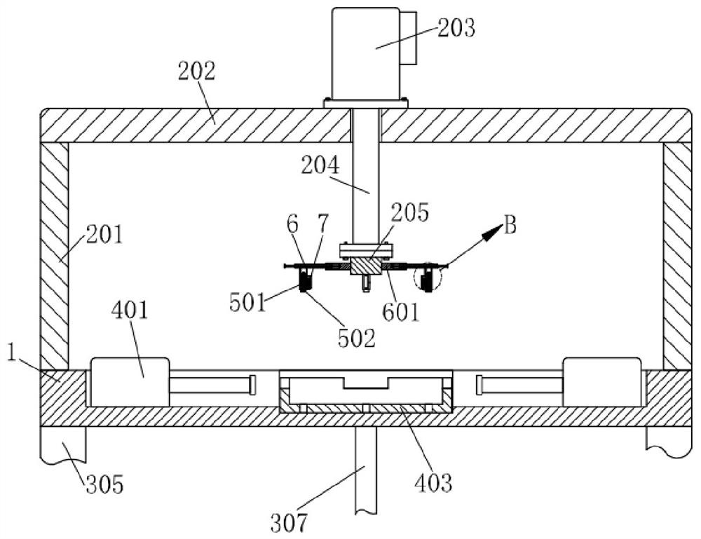
[0029] like Figure 1-Figure 6 As shown, a detection device for a motorcycle clutch according to the present invention includes a fixed plate 1 on which a drive mechanism 2 is installed, and a plurality of sets of adjustment mechanisms 6 are installed on the drive mechanism 2 at equal distances. A detection mechanism 5 is installed on a plurality of adjustment mechanisms 6, a marking mechanism 7 for marking the unqualified female thread holes is installed on a plurality of the detection mechanisms 5, and a clamping mechanism 4 is installed on the fixing plate 1, The clamping mechanism 4 corresponds to the detection mechanism 5, and a positioning mechanism 3 for positioning the detection object is installed on the fixing plate 1;

[0030] Speci...


PUM


Abstract

The invention relates to the technical field of clutch detection, in particular to a detection device for a motorcycle clutch, which includes a fixed plate, on which a driving mechanism is installed, and multiple sets of adjustment mechanisms are equidistantly installed on the driving mechanism. Each adjustment mechanism is equipped with a detection mechanism, and a plurality of detection mechanisms are equipped with a marking mechanism for marking the unqualified screw holes, and the clamping mechanism is installed on the fixed plate, and the fixed plate is equipped with a The positioning mechanism for positioning the detection object; multiple adjustment mechanisms are equidistantly installed on the driving mechanism, which is beneficial to the detection of detection objects of different sizes. After the clutch assembly to be detected is clamped, the detection mechanism is pushed by the driving mechanism, then the detection mechanism Realize the detection of the clutch component to be tested. When the clutch component is unqualified, the detection mechanism cannot be inserted into the screw hole, and some components of the detection mechanism shrink and conflict with the clutch component, and the unqualified screw hole can be clearly observed.

Description

technical field [0001] The invention relates to the technical field of clutch detection, in particular to a detection device for a motorcycle clutch. Background technique [0002] The clutch is a device that transmits the engine power of a car or other power machinery to the axle in a switch mode. The clutch is located in the flywheel housing between the engine and the gearbox. The clutch assembly is fixed on the rear plane of the flywheel with screws. The output shaft of the gearbox is the input shaft of the gearbox. The total clutch components are: clutch plate, clutch pressure plate, release sleeve, release bearing, return spring, clutch cable, clutch release fork, shell and other components. [0003] However, at present, the position of the screw hole of the clutch cover needs to be detected after the production of the clutch cover is completed. During the detection, the clutch cover is clamped by a clamp, and the produced cover is tested by the detection pin correspondi...

Claims


Application Information

Patent Timeline
Patent Type & Authority Patents(China)
IPC IPC(8): G01M13/022
CPCG01M13/022
Inventor 陈文进刘成勇
Owner JINAN HONGZHENG TECH
Why Eureka
Try Eureka