
Laser radar 3D point cloud ground detection method

A technology of laser radar and ground detection, which is applied in the direction of measuring devices, radio wave measuring systems, instruments, etc., can solve problems such as difficult to achieve the expected ground filtering effect, and achieve the effect of improving operating efficiency

Pending Publication Date: 2022-05-13
ZHEJIANG LEAPMOTOR TECH CO LTD
View PDF1 Cites 3 Cited by
  • Summary
  • Abstract
  • Description
  • Claims
  • Application Information

AI Technical Summary

Problems solved by technology

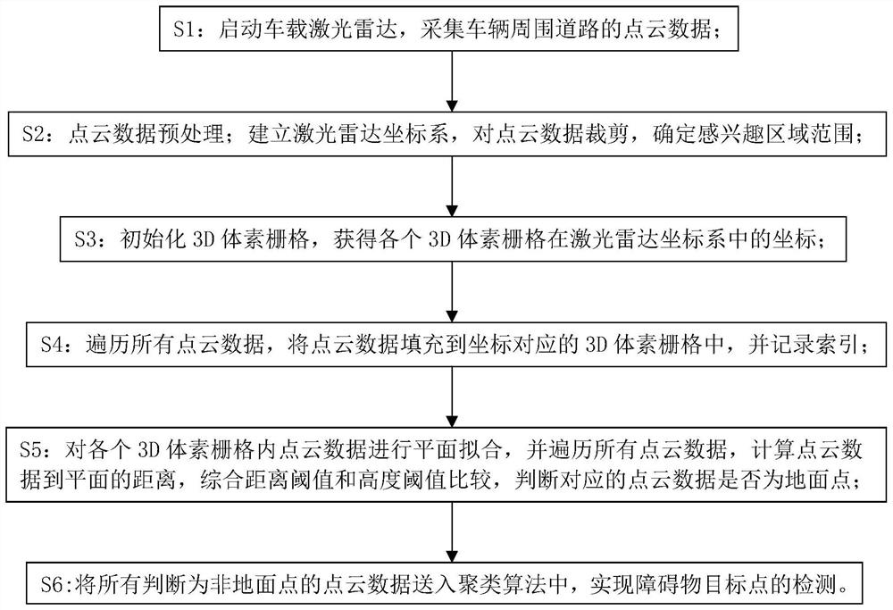
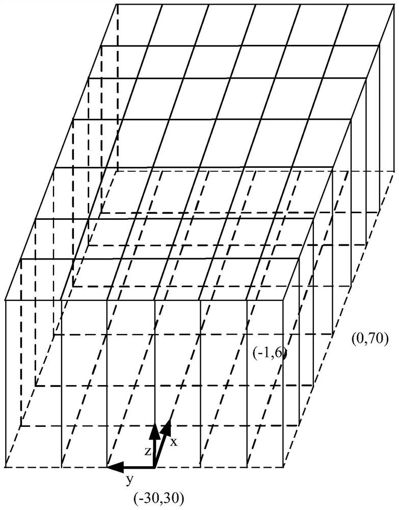
[0006] The present invention mainly solves the problem that the existing technology is difficult to achieve the expected ground filtering effect; it provides a ground detection method of 3D point cloud of laser radar, which divides the point cloud data into grids through 3D voxel grids, and then performs plane simulation Combine and other operations to extract ground points to achieve the expected ground filtering effect

Method used


Image

  • Laser radar 3D point cloud ground detection method
  • Laser radar 3D point cloud ground detection method

Examples


Embodiment 1

[0053] A kind of lidar 3D point cloud ground detection method of this embodiment, such as figure 1 shown, including the following steps:

[0054] S1: Start the on-board lidar to collect point cloud data of the roads around the vehicle.

[0055] After the lidar (mechanical or solid-state) is mounted on the vehicle, start the lidar drive, and the lidar will obtain the 3D point cloud data information of the surrounding roads while the vehicle is driving, and upload the point cloud data to the system for storage .

[0056]S2: Point cloud data preprocessing; establish the lidar coordinate system, cut out the point cloud data, and determine the scope of the region of interest.

[0057] After receiving the point cloud data, the point cloud data will be preprocessed.

[0058] The preprocessing of point cloud data includes clipping the point cloud data, leaving only the point cloud data within the region of interest. The scope of the region of interest is adjusted according to the ...

Embodiment 2

[0088] The solution of this embodiment optimizes step S5.

[0089] After the process of step S4, after obtaining the index and coordinates of the point cloud data in each 3D voxel grid in the lidar coordinate system, the point cloud data in the 3D voxel grid is converted into the two-dimensional coordinate system point, i.e. set all X values ​​to 0.

[0090] Sort the point cloud data according to the Z-axis coordinate value from small to large, and select the first five point cloud data;

[0091] Perform straight line fitting on the Y and Z coordinates of the selected five point cloud data. If there are ground points, a straight line will be fitted;

[0092] Calculate the distance from other point cloud data to the fitted straight line, if the calculated distance is less than the distance threshold D1, then judge the point cloud data to be a ground point, otherwise judge it to be a non-ground point.

[0093] In the solution of this embodiment, step S5 is optimized, and other...


PUM


Abstract

The invention discloses a laser radar 3D point cloud ground detection method. The problem that an expected ground filtering effect is difficult to achieve in the prior art is solved. The method comprises the following steps: collecting point cloud data of roads around a vehicle; cutting the point cloud data, and determining a region-of-interest range; initializing 3D voxel grids, and obtaining coordinates of each 3D voxel grid in a laser radar coordinate system; traversing all the point cloud data, filling 3D voxel grids corresponding to the coordinates with the point cloud data, and recording indexes; carrying out plane fitting on the point cloud data in each 3D voxel grid, traversing all the point cloud data, calculating the distance from the point cloud data to a plane, comparing a distance threshold value with a height threshold value, and judging whether the corresponding point cloud data is a ground point or not; and sending all point cloud data which are judged to be non-ground points into a clustering algorithm to realize detection of obstacle target points. And for a scene of a single voxel, ground points are identified and distinguished, and an expected ground filtering effect is achieved.

Description

technical field [0001] The invention relates to the field of laser radar detection, in particular to a ground detection method of a laser radar 3D point cloud. Background technique [0002] In recent years, with the development of smart technology, it has been applied in fields such as smart cars or robots. Under certain environmental conditions, the automatic driving of the vehicle can be realized. However, to realize autonomous driving technology, it is necessary to rely on a variety of sensors, such as cameras, lidar, millimeter-wave radar, etc., to perceive the information around the vehicle, and then to control the vehicle to drive within a safe range. This patent involves lidar, which can scan 3D information of objects and is an essential sensor for autonomous driving. [0003] However, when applying the traditional lidar target detection algorithm, one of the key processes is the detection of ground points. The quality of the ground detection results directly affect...

Claims


Application Information

Patent Timeline
IPC IPC(8): G01S17/931G01S7/495G06K9/62
CPCG01S17/931G01S7/495G06F18/23
Inventor 杨海涛
Owner ZHEJIANG LEAPMOTOR TECH CO LTD
Learn More