Supercharge Your Innovation With Domain-Expert AI Agents!

Cable bridge for electromechanical equipment

A technology for cable trays and electromechanical equipment, which is applied in the field of cable trays for electromechanical equipment, which can solve problems such as potential safety hazards, easy spread, and low safety performance, and achieve the effects of good safety, preventing fire from spreading, and improving safety

Pending Publication Date: 2022-05-13
临沂欧邦机电设备有限公司
View PDF0 Cites 0 Cited by
  • Summary
  • Abstract
  • Description
  • Claims
  • Application Information

AI Technical Summary

Problems solved by technology

[0003] Since electromechanical equipment usually needs to transmit electric energy and signals through cables, in order to prevent cables from being entangled with each other, cable trays are usually used to arrange cables, and the insulation layer of cables contains various combustible substances, which may cause fire. When multiple cables are laid in the cable tray, due to the close distance between adjacent cables and no isolation protection measures, when one of the cables catches fire, the fire will easily spread to the other cables, and the fire can spread rapidly. The safety performance is low, and there are great safety hazards

Method used


Image

  • Cable bridge for electromechanical equipment
  • Cable bridge for electromechanical equipment
  • Cable bridge for electromechanical equipment

Examples


Embodiment 1

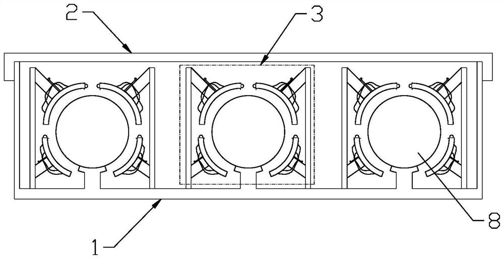
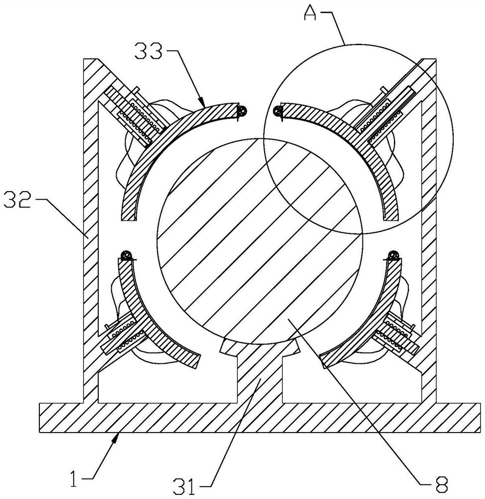
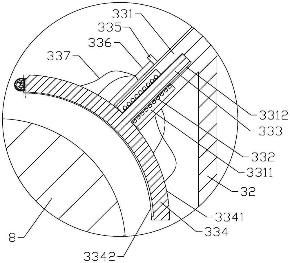
[0033] Embodiment one: if Figure 1-4As shown, a cable tray for electromechanical equipment includes a cable tray 1 and a protective cover 2, the protective cover 2 is covered on the cable tray 1, and the cable tray 1 is provided with at least two paving units for passing cables 8 3. The paving unit 3 includes a base 31 for supporting the cable 8 and two side plates 32, the two side plates 32 are distributed on both sides of the base 31, and two fire extinguishing assemblies 33 distributed up and down are arranged on the side plates 32 The fire extinguishing assembly 33 includes a mounting rod 331, a compression spring 332, a sliding rod 333, an arc plate 334, a positioning block 335, a thermal fuse 336 and a plurality of heat conducting wires 337, and one end of the mounting rod 331 is fixedly connected to the side plate 32, and the installation The other end of the rod 331 faces the position where the cable 8 is located. The other end of the mounting rod 331 is provided with...

Embodiment 2

[0041] Embodiment two: if Figure 7-11 As shown, the remaining parts are the same as in Embodiment 1, except that the two ends of the arc-shaped plate 334 along the circumferential direction are defined as the first end face 3344 and the second end face 3345, and the height of the first end face 3344 is higher than that of the second end face. At the height of the end face 3345, the first end face 3344 is provided with a first accommodating groove 3346, the first accommodating groove 3346 is provided with a fire extinguishing agent 4, and the inner concave arc surface 3342 of the arc plate 334 is provided with a second accommodating Groove 3347, the groove bottom of the second accommodating groove 3347 is provided with the groove 3348 that communicates with the first accommodating groove 3346, and the groove 3348 is located at the highest point of the second accommodating groove 3347, and the elastic member 5 is arranged in the groove 3348 And the slide plate 6, the slide plat...


PUM


Abstract

A cable bridge for electromechanical equipment disclosed by the present invention comprises a cable tray and a protective cover, the protective cover covers the cable tray, the cable tray is internally provided with at least two paving units for cables to pass through, each paving unit comprises a base for supporting the cables and two side plates, and the two side plates are arranged on the base. Two fire extinguishing assemblies which are distributed up and down are arranged on the side plate, each fire extinguishing assembly comprises a mounting rod, a compression spring, a sliding rod, an arc-shaped plate, a positioning block, a hot melting wire and a plurality of heat conduction wires, and in one paving unit, when the heat conduction wires are heated and enable the hot melting wires to be fused, the compression springs push the arc-shaped plates and the sliding rods to move in the direction where the cable is located; the arc-shaped plate is finally attached to the side surface of the cable; when all the hot melting wires are fused, all the arc-shaped plates are pushed to be attached to the side face of the cable through the compression spring, and all the arc-shaped plates and the base are matched to form a sleeve tightly attached to the cable. The method has the advantage of being good in safety.

Description

technical field [0001] The invention belongs to the technical field of electrical equipment accessories, in particular to a cable tray for electromechanical equipment. Background technique [0002] Electromechanical equipment generally refers to machinery, electrical appliances, and electrical automation equipment. In construction, it refers to the general term for machinery and pipeline equipment other than geotechnical, carpentry, steel bars, and muddy water. With the continuous improvement of people's living standards, people's demand for electromechanical equipment in daily life is increasing. [0003] Since electromechanical equipment usually needs to transmit electric energy and signals through cables, in order to prevent cables from being entangled with each other, cable trays are usually used to arrange cables, and the insulation layer of cables contains various combustible substances, which may cause fire. When multiple cables are laid in the cable tray, due to the...

Claims


Application Information

Patent Timeline
Patent Type & Authority Applications(China)
IPC IPC(8): H02G3/32A62C3/16A62C37/11
CPCH02G3/32A62C3/16A62C37/11
Inventor 章爱伟
Owner 临沂欧邦机电设备有限公司
Features
  • R&D
  • Intellectual Property
  • Life Sciences
  • Materials
  • Tech Scout
  • Unparalleled Data Quality
  • Higher Quality Content
  • 60% Fewer Hallucinations
Learn More