Rotating structure and folding rotating rod piece

A technology of rotating structure and rotating direction, which is applied in the field of rotating structure and folding rotating rods, which can solve the problems of inconvenient operation and achieve the effects of simple automatic reset, good positioning and stop, and fast sliding reset

Pending Publication Date: 2022-05-17
安徽兴腾物流设备有限公司
View PDF11 Cites 0 Cited by
  • Summary
  • Abstract
  • Description
  • Claims
  • Application Information

AI Technical Summary

Problems solved by technology

[0003] The purpose of the present invention is to provide a rotating structure and a folding rotating rod, aiming to solve the technical problem of inconvenient operation existing in the existing rotating structure

Method used


Image

  • Rotating structure and folding rotating rod piece
  • Rotating structure and folding rotating rod piece
  • Rotating structure and folding rotating rod piece

Examples


Embodiment 1

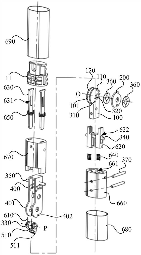
[0066] Please refer to figure 1 and figure 2 , the rotating structure includes a first fixing seat 100 , a return element 200 , a second fixing seat 400 , a non-return element 510 and a first elastic member 610 .

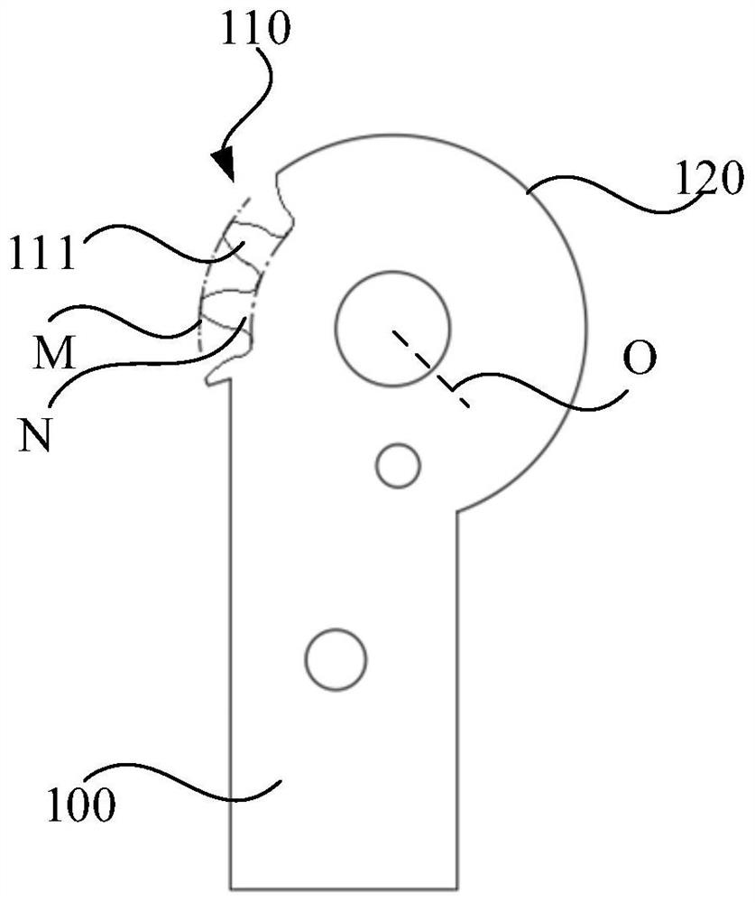
[0067] Please refer to image 3 and Figure 4 , the first end of the first fixing base 100 has a gear segment 110 and a first arc segment 120 distributed around the first axis O. The return element 200 is configured to be swingably mounted on the first fixing base 100 around the first axis O. The return element 200 has a second arc segment 210 and a third arc segment 220 distributed around the first axis O. The diameter of the second arc segment 210 is greater than or equal to the diameter M of the top circle of the gear segment 110 , and the diameter of the third arc segment 220 is less than or equal to the diameter N of the root circle of the gear segment 110 .

[0068] Optionally, the number of teeth of the gear segment 110 is more than one. For example, th...

Embodiment 2

[0137] Please combine figure 1 , figure 2 and Figure 12, the rotating structure includes a first fixing base 100 , a second fixing base 400 , a non-return element 510 and a first elastic member 610 .

[0138] The first end of the first fixing seat 100 has a gear segment 110 and a first arc segment 120 distributed around the first axis O, and the gear segment 110 has a gear tooth 111 . The second fixing base 400 is configured to be rotatably mounted on the first fixing base 100 around the first axis O. The non-return element 510 is configured to be rotatably mounted on the second fixed seat 400 around the second axis P, the second axis P is parallel to the first axis O, the non-return element 510 can abut against the gear segment 110, so that the second The fixing seat 400 rotates in one direction around the first axis O along the first rotation direction. The first elastic member 610 is installed on the second fixing base 400, and the first elastic member 610 is used to ...

Embodiment 3

[0143] The rotating structures in Embodiment 1 and Embodiment 2 can be applied to the rotating connection between two structures. For example, a swivel connection between a door and a door frame, a swivel connection between a tray 20 and a rod 10, or a swivel folding connection in furniture.

[0144] Specifically, the first fixing base 100 is connected to one of the structures, and the second fixing base 400 is connected to the other structure, so as to realize the rotational connection between the two structures.

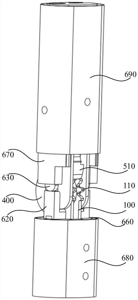
[0145] Please refer to Figure 16 and Figure 17 , the present invention also provides a foldable rotating rod, including the rod 10 and any one of the above rotating structures. The rod 10 is connected with the second fixing seat 400 .

[0146] The folding rotating rod can be applied to a folding bicycle, a folding stroller or a folding cart.

[0147] Specifically, the folding rotating rod further includes a tray 20, which is fixedly connected with the first f...


PUM


Abstract

The invention relates to the technical field of rotating structures, and provides a rotating structure and a folding rotating rod piece, the rotating structure comprises a first fixed seat, a return element, a second fixed seat, a non-return element and a first elastic piece, the first end of the first fixed seat is provided with a gear section and a first arc section which are distributed around a first axis; the return element is provided with a second arc section and a third arc section which are distributed around the first axis; the second fixing seat is configured to be rotatably mounted on the first fixing seat around a first axis; the non-return element is configured to be rotatably mounted on the second fixing seat around a second axis, and the non-return element can abut against the gear section so as to enable the second fixing seat to rotate in a single direction around the first axis in the first rotating direction; the first elastic piece is used for applying elastic force to the non-return element so that the non-return element can rotate around the second axis in the second rotating direction, and the second rotating direction is opposite to the first rotating direction. The rotating structure provided by the invention solves the technical problem that an existing rotating structure is inconvenient to operate.

Description

technical field [0001] The invention relates to the technical field of rotating structures, in particular to a rotating structure and a folding rotating rod. Background technique [0002] Among the existing rotating structures and products containing the rotating structures, such as folding rotating rods, the folding rotating rods can be applied to folding bicycles, folding carts, folding carts, folding luggage and so on. In this type of product, the rod is unfolded and fixed on the chassis through a slot or a latch. When the rod needs to be rotated and folded, the fixed relationship between the rod and the chassis can be released by releasing the restriction of the slot or latch to achieve the Pieces are rotated for folding purposes. However, when releasing the fixing restriction of the rod, it is necessary to squat down and manually operate the fixed position (such as the slot or the latch), which is generally located at the bottom of the rod, and the operation is complic...

Claims


Application Information

Patent Timeline
Patent Type & Authority Applications(China)
IPC IPC(8): B62K15/00B62B3/02
CPCB62K15/00B62B3/02
Inventor 范福林颜飞李正陈小明彭留港章佳美陶子凡
Owner 安徽兴腾物流设备有限公司
Why Eureka
Try Eureka