Transformer tap switch protection method based on built-in current and temperature sensor

A technology of temperature sensor and tap changer, which is applied in the field of power system, can solve problems such as explosion, long operating time, and damage to converter transformers, and achieve the effect of solving low sensitivity

Pending Publication Date: 2022-05-17
NR ELECTRIC CO LTD +2
View PDF0 Cites 0 Cited by
  • Summary
  • Abstract
  • Description
  • Claims
  • Application Information

AI Technical Summary

Problems solved by technology

[0003] In engineering, transformers are usually equipped with electrical quantity protection and non-electrical quantity protection, which can reflect various internal short-circuit faults and grounding faults of the transformer; however, there are low sensitivity and poor quick action to short-circuit faults at the transformer tap changer. insufficient
In recent years, there have been many short-circuit faults of converter transformer tap changers. Due to the long operating time of the configured electric quantity protection and non-electric quantity protection, the converter transformer has been seriously damaged, and even exploded, causing more serious accidents.
The key reason is that there is no special current transformer and temperature sensor installed at the tap changer of the transformer, so that when a slight fault occurs at the tap changer, the traditional electrical quantity protection and non-electrical quantity protection cannot respond; The traditional electrical protection and non-electrical protection can only operate when the fault of the connecting switch develops further and spreads to the transformer body

Method used


Image

  • Transformer tap switch protection method based on built-in current and temperature sensor

Examples


Embodiment Construction

[0028] In order to make the object, technical solution and advantages of the present invention more clear, the present invention will be further described in detail below in conjunction with the examples. It should be understood that the specific embodiments described here are only used to explain the present invention, not to limit the present invention.

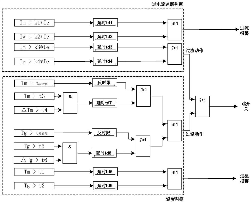
[0029] Such as figure 1 Shown is the logic diagram of the transformer tap changer fast protection. A kind of transformer tap changer protection method based on built-in current and temperature sensor of the present invention, comprises the following steps:

[0030] (1) Step 1

[0031] Install built-in current and temperature sensors in the main on-off contact (MSV for short) and transition contact (TTV for short) of the transformer tap changer, and collect the current and temperature of the main on-off contact and transition contact at the same time;

[0032] (2) Step 2

[0033] Calculate the current of the main on-off ...


PUM


Abstract

The invention discloses a transformer tap switch protection method based on built-in current and temperature sensors, and the method comprises the steps: installing the built-in current and temperature sensors in a main on-off contact MSV and a transition contact TTV of a transformer tap switch, and collecting the current and temperature of the main on-off contact and the transition contact; calculating the current of the main on-off contact and the transition contact to form an over-current quick-break criterion of the transformer tap switch; and calculating the temperature of the main on-off contact and the transition contact to form the temperature criterion of the tap switch of the transformer. And when the over-current quick-break criterion or the temperature criterion of the transformer tap switch is met, the transformer tap switch performs protection action, and acts on an alarm signal and a trip switch respectively according to the severity of the fault. According to the invention, slight faults of the transformer tap switch can be sensitively identified and rapid action can be realized.

Description

technical field [0001] The invention relates to the design of transformer protection in the field of power systems, in particular to a transformer tap changer protection method based on built-in current and temperature sensors. Background technique [0002] In modern large-scale power systems, transformers are widely used to increase or decrease voltage, and are the main electrical equipment in modern large-scale power systems. It is expensive to manufacture, and it will seriously affect the reliability of power supply after failure, and even threaten the safe and stable operation of the entire power system. The tap changer is the core component of the transformer to complete online voltage regulation; at the same time, it is also a fault-prone component of the transformer, especially the tap changer of the converter transformer. [0003] In engineering, transformers are usually equipped with electrical quantity protection and non-electrical quantity protection, which can r...

Claims


Application Information

Patent Timeline
IPC IPC(8): H02H3/08H02H5/04H02H7/04
CPCH02H7/04H02H3/08H02H5/04
Inventor 莫品豪张晓宇顾乔根吕玮郑超程骁顾朝亮孙仲民曾亮
Owner NR ELECTRIC CO LTD
Why Eureka
Try Eureka