
Self-flowing swivel for concrete sand and gravel recovery and separation

A concrete and gravel technology, which is applied in the field of self-passing rotary parts, can solve the problems of no through holes and easy blockage of the mesh, and achieve the effect of reducing wear and saving grinding time

Active Publication Date: 2022-07-19
山西辰润交通科技有限公司
View PDF7 Cites 0 Cited by
  • Summary
  • Abstract
  • Description
  • Claims
  • Application Information

AI Technical Summary

Problems solved by technology

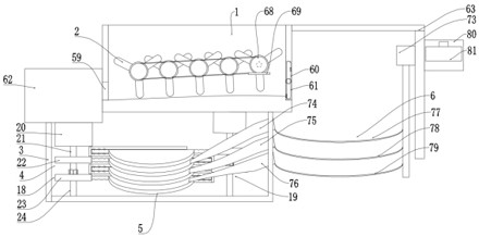
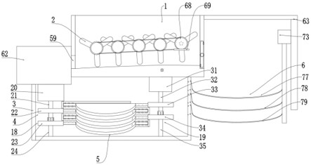
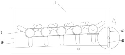
[0005] The technical scheme adopted by the present invention is as follows: The self-passing rotary part for recycling and separating concrete sand and gravel provided by the present invention includes a concrete separation box, a self-passing rotary separation and recovery device, a sandstone grinding box, a grinding drive assembly, a hedging type Two-way pressing and grinding device and screen assembly, the self-passing rotary separation and recovery device is movable in the concrete separation box, the concrete separation box supports and fixes the self-passing rotary separation and recovery device, and the self-passing rotary separation and recovery device can be The rotary method separates the sand and gravel in the concrete as a whole, and at the same time, it can realize the self-shrinking and adsorption opening and closing working process during the separation, which solves the problem that the existing device is easy to block the mesh during separation. The problem is to achieve the technical effect of not only having a through hole, but also not having a through hole to prevent clogging; the sandstone grinding box is connected to the bottom wall of the concrete separation box, and the opposite-type two-way pressing and grinding device is movable in the sandstone grinding box Inside, the sandstone grinding box plays a supporting role, and the opposite-type two-way pressing and grinding device realizes sandstone grinding of different sizes at the same time in a stacked manner. The grinding drive assembly is arranged in the sandstone grinding box. The hedge type two-way grinding device is meshed and connected, and the work of the grinding drive component drives the hedge type two-way grinding device to rotate in the opposite direction. At the same time, the grinding drive component can adjust the hardness of the driving gear according to the demand, and can regulate the grinding time of small sand and gravel to prevent When the large sandstone is polished for a long time, the small sandstone will be continuously polished to cause additional waste; one end of the screen assembly is connected to the concrete separation box, and the other end of the screen assembly is connected to the sandstone grinding box, and the screen assembly The sieved stones are screened, and the classified stones are led to the hedge-type two-way grinding device for classified grinding; Revolving part, revolving connecting roller and connecting roller driving assembly, the revolving connecting roller is movable in the concrete separation box, the concrete separating box supports the revolving connecting roller, and a rotating seal is arranged between the revolving connecting roller and the concrete separating box , while the rotary connecting roller can rotate, it can ensure the sealing between the rotary connecting roller and the concrete separation box. The connecting roller drive assembly is movable on the outer wall of the concrete separation box. Connected, the concrete separation box and the rotary connecting roller support the connecting roller driving assembly, and the connecting roller driving assembly drives the rotary connecting roller. group, several groups of self-passing rotary parts are evenly arranged on the rotary connecting roller at equal intervals, and the rotary connecting roller supports and drives the self-passing rotary part. On the revolving connecting roller; the driving assembly of the connecting roller drives the revolving connecting roller to rotate, and the revolving connecting roller drives the self-passing revolving part and the folding self-passing assembly to rotate in the same direction in a manner interlaced with each other, and the folding self-passing assembly can regulate each other The spacing between the screens prevents the clogging of the sieve plate during the separation of the concrete, and at the same time, the sand and gravel can be recycled

Method used


Image

  • Self-flowing swivel for concrete sand and gravel recovery and separation
  • Self-flowing swivel for concrete sand and gravel recovery and separation
  • Self-flowing swivel for concrete sand and gravel recovery and separation

Examples


Embodiment Construction

[0042] The technical solutions in the embodiments of the present invention will be clearly and completely described below with reference to the accompanying drawings in the embodiments of the present invention. Obviously, the described embodiments are only a part of the embodiments of the present invention, rather than all the embodiments; based on the The embodiments of the present invention, and all other embodiments obtained by those of ordinary skill in the art without creative efforts, fall within the protection scope of the present invention.

[0043] In the description of the present invention, it should be understood that the terms "upper", "lower", "front", "rear", "left", "right", "top", "bottom", "inside", " "Outside" and other indications of orientation or positional relationship are based on the orientation or positional relationship shown in the accompanying drawings, which are only for the convenience of describing the present invention and simplifying the descri...


PUM


Abstract

The invention discloses a self-passing rotary member for recycling and separating concrete sand and gravel, comprising a concrete separation box, a self-passing rotary separation and recovery device, a sand and gravel grinding box, a grinding drive assembly, a counter-type two-way pressure grinding device and a screen assembly , the self-passing type rotary separation and recovery device is movably arranged in the concrete separation box; the sand and gravel grinding box is connected to the bottom wall of the concrete separation box, and the counter-type two-way pressure grinding device is movably arranged in the sand and gravel grinding box, and the The grinding drive assembly is arranged in the sand and gravel grinding box, and the grinding drive assembly is engaged with the counter-type two-way pressure grinding device; one end of the screen assembly is connected to the concrete separation box, and the other end of the screen assembly is connected to the sand and gravel. The grinding box is connected through. The invention belongs to the technical field of concrete recycling equipment, and specifically refers to a self-flow gyratory piece for recycling and separating concrete sand and gravel;

Description

technical field [0001] The invention belongs to the technical field of concrete recycling equipment, in particular to a self-flowing rotary member used for recycling and separating concrete sand and gravel. Background technique [0002] Concrete is a mixture of cement, granular aggregates, water, and chemical admixtures and mineral admixtures that need to be added in appropriate proportions. It is widely used in civil engineering. Concrete is often used in excess, and the remaining concrete can only be discarded due to its own characteristics, resulting in waste of resources and environmental pollution. At the same time, when concrete is transported by a mixer truck, the mixer truck needs to be cleaned regularly due to the characteristics of concrete. In this way, a large amount of waste water will be generated. On the one hand, these construction wastes and waste water waste a lot of resources, and on the other hand, they cause soil and groundwater pollution. Therefore, the...

Claims


Application Information

Patent Timeline
Patent Type & Authority Patents(China)
IPC IPC(8): B02C4/08B02C4/42B02C4/28B02C4/32B02C4/40B02C23/14B02C21/00
CPCB02C4/08B02C4/42B02C4/28B02C4/32B02C4/40B02C23/14B02C21/00Y02W30/91
Inventor 王永强寇文亮张胜利张海林王素芹李晓张素霞程磊王彩莉梁飞康晋芳刘俊爱牛慧芳吴喆娜李艳国
Owner 山西辰润交通科技有限公司
Learn More