Supercharge Your Innovation With Domain-Expert AI Agents!

Light path correction method of correlation type sensor and gate equipment

A sensor and proximity sensor technology, applied in the optical field, can solve problems such as false sensing of gate equipment

Pending Publication Date: 2022-05-24
SHANGHAI HUAMING INTELLIGENT TERMINAL EQUIP
View PDF0 Cites 4 Cited by
  • Summary
  • Abstract
  • Description
  • Claims
  • Application Information

AI Technical Summary

Problems solved by technology

[0003] Existing gate equipment usually uses through-beam sensors to sense the human body. However, in the prior art, since most sensors use through-beam sensors, and the transmitter of the sensor emits sensing rays, it senses Rays spread in a divergent manner, and when they irradiate the receiving end of the sensor, a large area of ​​illumination will be formed. Therefore, when the receiving end of the optical path of the sensor is arranged densely, some problems are likely to occur in actual use. The phenomenon that the sensing rays sent by the transmitting end of a sensor are received by the receiving end of the adjacent sensor, so that the gate equipment produces false induction

Method used


Image

  • Light path correction method of correlation type sensor and gate equipment
  • Light path correction method of correlation type sensor and gate equipment
  • Light path correction method of correlation type sensor and gate equipment

Examples


Embodiment 2

[0128] This embodiment provides an optical path deviation correction method for a through-beam sensor. This embodiment is substantially the same as the above-mentioned first embodiment, and the differences are as follows in this embodiment. Figure 19 to Figure 21 As shown, in step S3, that is, the step of arranging a light-shielding member with a light-transmitting slit on one side adjacent to the emission end of the sensor includes the following steps:

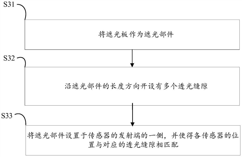
[0129] Step S31 ': use several shading blocks 1 ' as shading parts, wherein, each shading block 1 ' is provided with at least one light-transmitting slit, wherein, the opening direction of light-transmitting slit 10 is perpendicular to the length direction;

[0130] Step S32': each light-shielding block 1' is arranged on one side of the transmitting end of the sensor in turn, and the position of each sensor is matched with the corresponding light-transmitting slit.

[0131] Step S33 ': each shading block 1 ' is arranged alon...

Embodiment 3

[0135] This embodiment provides an optical path deviation correction method for a through-beam sensor. This embodiment is a further improvement to any of the above-mentioned embodiments. The improvements in this embodiment are as follows: Figure 22 to Figure 25 As shown, before or after the step of arranging the light-shielding member 1 with the light-transmitting slit on one side adjacent to the emission end of the sensor, the steps further include:

[0136] Step S4: by sliding the light blocking member 15 arranged on the light shielding member 1, slide to a preset position along the length direction of the light shielding member 1 to shield a part of the light transmission slot 10, thereby adjusting the width of the light transmission slot to the target Width to realize the dynamic adjustment of the width of the light-transmitting slit to meet the actual design and requirements, especially for a single light-transmitting slit or multiple light-transmitting slits. Large and ...

Embodiment 4

[0142] The present application also provides a gate device, which controls the illumination area by the optical path correction method of the through-beam sensor in any of the above embodiments; wherein the sensor is a sensor on the gate device for detecting the passage of human beings.

[0143] Compared with the prior art, the gate device provided by the present application can avoid the sensing rays emitted by the transmitting end of the sensor used to detect the passage of the human body on the gate device from being induced by the receiving end of the adjacent sensor, thereby avoiding the occurrence of misjudgment phenomenon.


PUM


Abstract

The invention aims to provide a light path correction method for correlation type sensors and gate equipment, and the correction method comprises the following steps: determining the structural parameters of a light-transmitting gap according to the distance between the receiving ends of two adjacent sensors on the gate equipment and the distance between the transmitting end and the receiving end of each sensor, the structural parameters at least comprise the width of the light-transmitting gap and the length of the narrow gap channel; sensing rays emitted by the emitting end of the sensor are restrained by the light-transmitting gap to form an illumination area covering the receiving end corresponding to the emitting end. And a shading part with a light-transmitting gap is arranged on one side of the transmitting end of the adjacent sensor. Compared with the prior art, the sensing ray emitted by the emitting end of the correlation type sensor can be prevented from being sensed by the receiving end of the adjacent sensor.

Description

technical field [0001] The invention relates to the field of optics, in particular to an optical path deviation correction method and a gate device of a through-beam sensor. Background technique [0002] In the existing passing equipment and other equipment, such as gate equipment, it is usually necessary to use a plurality of through-beam sensors to detect the passing of a human body or an object. [0003] Existing gate equipment usually uses through-beam sensors to sense the human body. However, in the prior art, because most sensors use through-beam sensors, and the transmitting end of the sensor emits the sensing rays, it senses the human body. The ray propagates in a divergent manner, and when it is irradiated to the receiving end side of the sensor, a large area of ​​illumination will be formed. Therefore, when the receiving end of the optical path of the sensor is densely arranged, it is very easy to appear in actual use. The phenomenon that the sensing ray sent by t...

Claims


Application Information

Patent Timeline
Patent Type & Authority Applications(China)
IPC IPC(8): G01V8/20E01F13/04
CPCG01V8/20E01F13/04
Inventor 张亮马四龙张炎潘伟
Owner SHANGHAI HUAMING INTELLIGENT TERMINAL EQUIP
Features
  • R&D
  • Intellectual Property
  • Life Sciences
  • Materials
  • Tech Scout
  • Unparalleled Data Quality
  • Higher Quality Content
  • 60% Fewer Hallucinations
Learn More