Dental treatment device

A treatment device, dental technology, applied in the direction of treatment, dentistry, physical therapy, etc., can solve the problems of different shapes, complex shapes, etc.

Pending Publication Date: 2022-05-27
MORITA MFG CO LTD
View PDF1 Cites 0 Cited by
  • Summary
  • Abstract
  • Description
  • Claims
  • Application Information

AI Technical Summary

Problems solved by technology

[0003] However, the shape of the root canal is complicated, and the shape varies depending on the type of tooth and also varies from person to person

Method used


Image

  • Dental treatment device
  • Dental treatment device
  • Dental treatment device

Examples


Embodiment approach 1

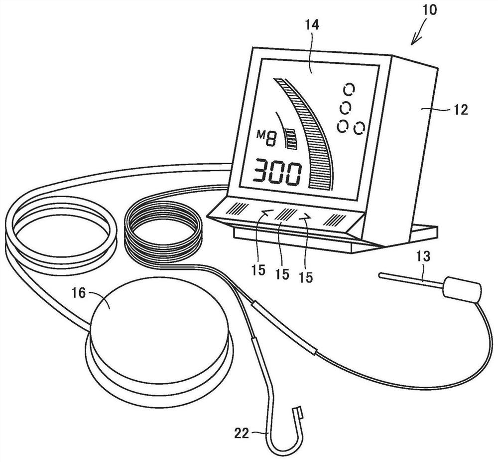
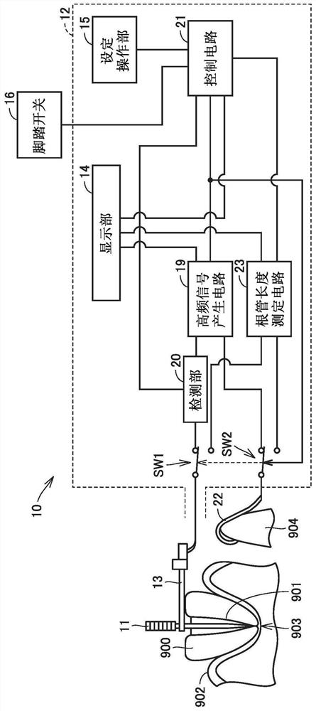
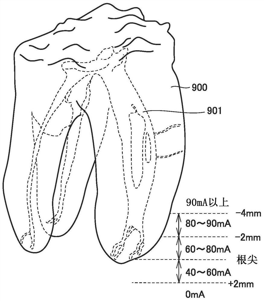
[0023] figure 1 An external view of the dental treatment apparatus according to Embodiment 1 is shown. figure 2 It is a block diagram showing the structure of the dental treatment apparatus according to the first embodiment. image 3 It is a schematic diagram for explaining the root canal of a tooth. The degree of root canal curvature and the state of root canal calcification and occlusion vary from person to person. Root canal treatment in which the root canal of a tooth is cut and enlarged is a very difficult treatment. image 3 The tooth 900 shown is a molar containing a plurality of root canals 901 in one tooth. It is difficult to treat all such complex-shaped root canals. In particular, when there is a portion where it is difficult to cut and expand the root canal using a cutting tool such as a reamer or a file, and the root canal cannot be cut and expanded in this portion, pulp and inflammatory factors may remain in the root canal. Inflammation after surgery.

[00...

Embodiment approach 2

[0051] In Embodiment 1, a dental treatment apparatus that energizes the file 11 with a high-frequency current of a preset current value in the sterilization mode based on information on the position of the distal end of the file 11 measured in the root canal length measurement mode 10 is described. In Embodiment 2, control of the current value of the high-frequency current to be energized to the file 11 in the sterilization mode will be described in detail. In addition, in Embodiment 2, the same reference numerals are attached to the same structure as the structure of the dental treatment apparatus 10 already demonstrated in Embodiment 1, and a detailed description is not repeated. In addition, the content described in the first embodiment and the second embodiment can be combined within a range that does not contradict each other.

[0052] Control of the current value of the high-frequency current that is applied to the file 11 in the dental treatment apparatus 10 will be de...

Embodiment approach 3

[0077] In Embodiment 1, the dental treatment apparatus 10 in which a high-frequency current of a preset current value is energized to the file 11 based on information on the position of the distal end of the file 11 measured in the root canal length measurement mode has been described. In the dental treatment apparatus according to Embodiment 3, the data is not only based on the information on the position of the distal end of the file 11 measured in the root canal length measurement mode, but also based on the position of the distal end of the file 11 measured during the rest period. The information control of the file energizes the structure during the energization of the high-frequency current. In addition, in Embodiment 3, the same code|symbol is attached|subjected to the same structure as the structure of the dental treatment apparatus 10 demonstrated in Embodiment 1, and a detailed description is not repeated. In addition, the contents described in Embodiment 1 and Embod...


PUM


Abstract

A dental treatment device (10) is provided with a file holder (13), a high-frequency signal generation circuit (19), a root canal length measurement circuit (23), and a control circuit (21). The file holder (13) holds a file (11) disposed in a root canal. The high-frequency signal generation circuit (19) supplies a high-frequency current to the file (11). The root canal length measurement circuit (23) electrically measures the position of the tip of the file (11) in the root canal. The control circuit (21) controls the current value of the high-frequency current energizing the file (11) in the high-frequency signal generation circuit (19) on the basis of the information about the position of the tip of the file (11) measured by the root canal length measurement circuit (23).

Description

technical field [0001] The present invention relates to a dental treatment apparatus for energizing a dental treatment site with a high-frequency current. Background technique [0002] In the dental field, a root canal treatment of a tooth is sometimes performed in order to remove the pulp or to suppress inflammation of the root tip. In the conventional root canal treatment, the root canal is cut and enlarged with a reamer and a file, and after the contamination tissue or contaminant in the root canal is removed, the root canal is filled with medicine. [0003] However, the shape of the root canal is complicated, and the shape varies from person to person depending on the type of tooth. Therefore, in root canal treatment, there are parts where it is difficult to enlarge the root canal using a reamer and a file, and inflammatory factors remain in the part where root canal enlargement cannot be performed, which may cause inflammation after surgery. [0004] Therefore, Japane...

Claims


Application Information

Patent Timeline
Patent Type & Authority Applications(China)
IPC IPC(8): A61C5/40A61C19/04A61C19/06A61N1/36
CPCA61C5/40A61C19/06A61C19/04A61N1/3605A61N1/326A61C5/42A61N1/06A61C19/041A61C5/44A61B18/1233A61B18/14A61B2018/00595A61B2018/00642A61B2018/00702A61B2018/0072A61B2018/00732A61B2018/00738A61B2018/00779A61C19/042
Inventor 植田智朗安达幸一郎的场一成
Owner MORITA MFG CO LTD
Why Eureka
Try Eureka