
Buffer structure for lifting strength training equipment

A technology of training equipment and cushioning structure, applied in the field of training equipment, can solve problems such as easy vibration, rope wear, breakage, etc., and achieve the effect of avoiding damage to equipment

Pending Publication Date: 2022-05-27
徐州力诺健康科技有限公司
View PDF5 Cites 0 Cited by
  • Summary
  • Abstract
  • Description
  • Claims
  • Application Information

AI Technical Summary

Problems solved by technology

[0004] In order to solve the above-mentioned technical problems, a method is provided. This technical solution solves the problem that when the existing lifting strength training device proposed in the above-mentioned background technology is used for a long time, the usually pulled ropes will be worn and broken, and the ropes cannot be broken. When the counterweight is fixed and kept on the original position, the falling counterweight will injure the personnel around the equipment and damage the equipment or the ground, and the existing lifting strength training equipment usually loses weight when the counterweight descends. In order to fall on the equipment or the ground, it is impossible to reduce the impact on the ground and the equipment through the buffer structure, which will cause the weight to fall and hit the equipment or the ground, which will easily cause vibration and cause discomfort to the trainers.

Method used


Image

  • Buffer structure for lifting strength training equipment
  • Buffer structure for lifting strength training equipment
  • Buffer structure for lifting strength training equipment

Examples


Embodiment 1

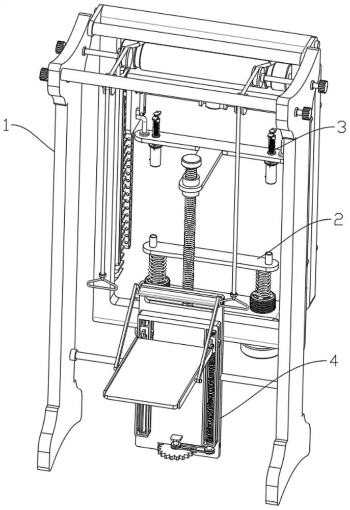
[0034] Please refer to figure 2 As shown, a buffer structure for lifting strength training equipment includes a gantry frame 1, the rear end of the gantry frame 1 is provided with an anti-fall pulling mechanism 2, and the left end of the anti-fall pulling mechanism 2 is provided with a drop buffering lever mechanism 3 , The lower end of the anti-fall pulling mechanism 2 is provided with a standing and sitting training adjustment mechanism 4 .

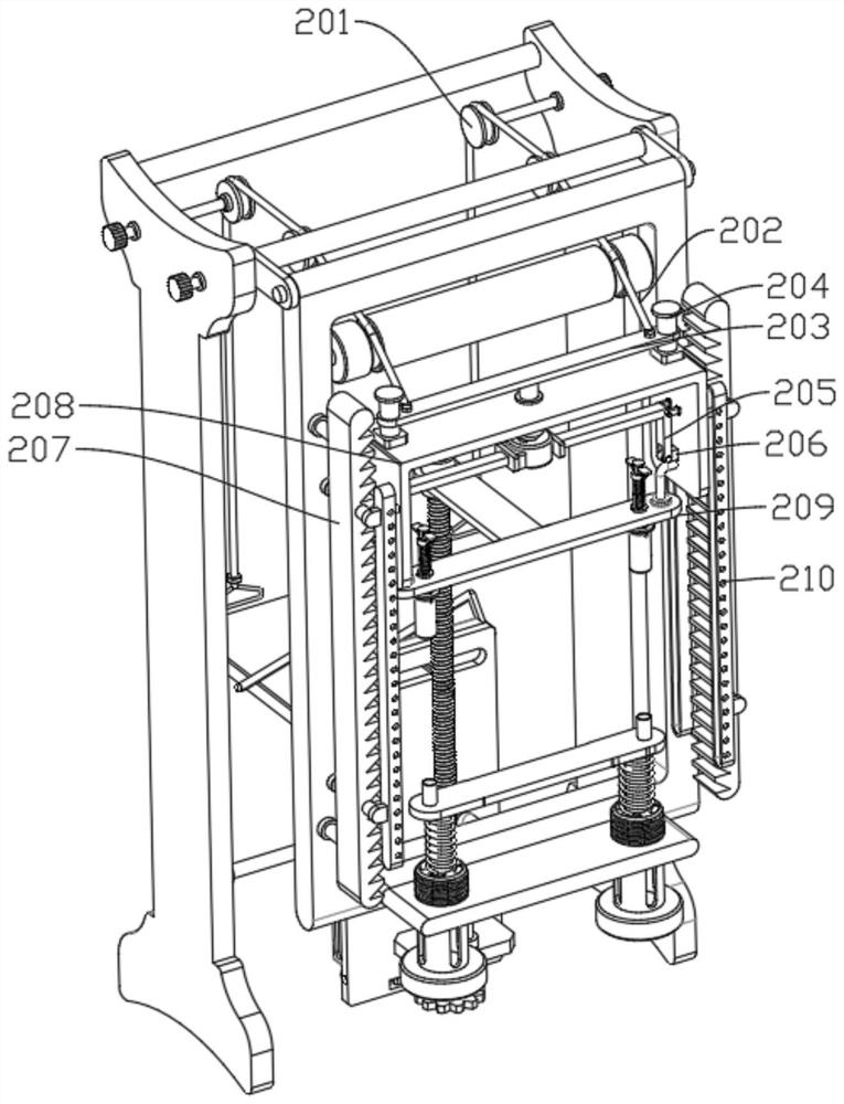
[0035]Preferably, the anti-fall pulling mechanism 2 includes a positioning roller 201, a pulling rope 202, a spring long plate 203, a dynamic positioning rod 204, a bending rod 205, a slope positioning rod 206, a plane sawtooth plate 207, and the inner walls of the left and right ends of the gantry 1 A positioning roller mechanism 201 is rotatably connected to each other, and a pull rope 202 is slidably connected to the outer surface of one end of the positioning roller 201. A groove shell 208 is fixedly connected to the lower end of ...

Embodiment 2

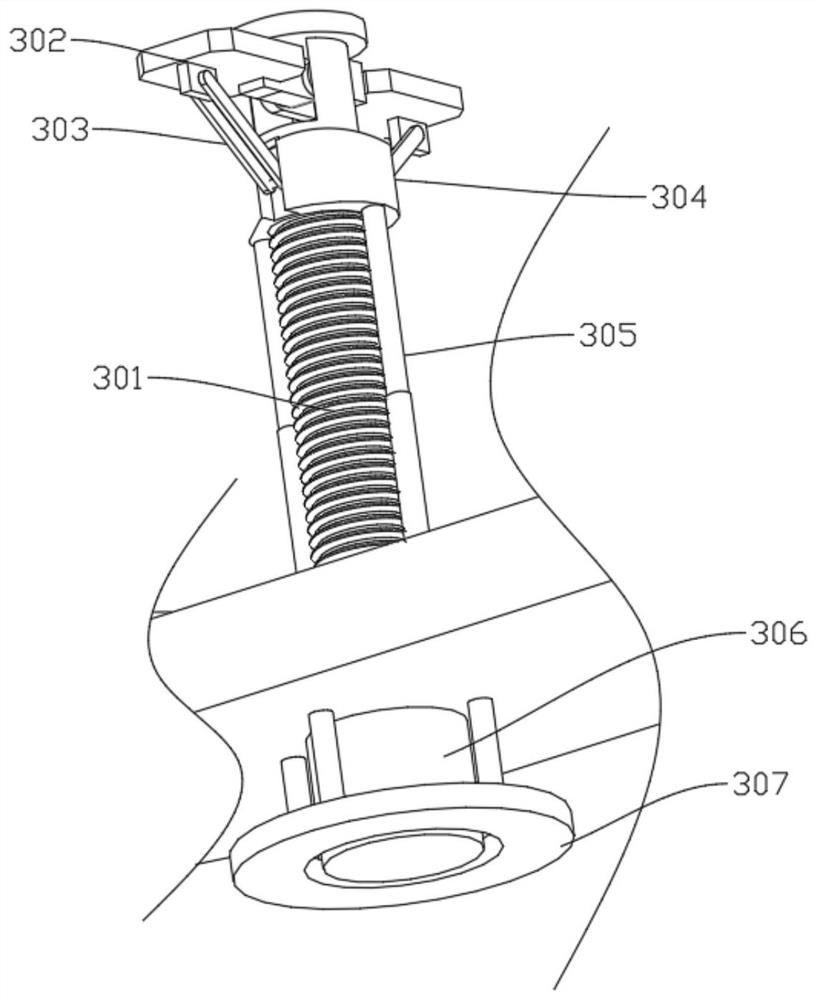
[0038] Please refer to image 3 Figure 4 and Figure 5 and Image 6 and Figure 7 As shown, the drop buffer opening mechanism 3 includes a short screw 301, a grid baffle 302, a support rod 303, a power internal thread sleeve 304, a telescopic rod 305, a turning plate 306, a positioning ring 307, and the left and right ends of the counterweight plate 209 are fixed. A short screw 301 is connected, the upper end of the short screw 301 is rotatably connected with a grid baffle 302, the front and rear ends of the grid baffle 302 are rotatably connected with a support rod 303, and the lower end of the support rod 303 is rotatably connected with a power internal thread sleeve 304, a power internal thread sleeve The lower end of 304 is fixedly connected with a telescopic rod 305, the lower end of the telescopic rod 305 is fixedly connected with a rotating plate 306, the lower end of the rotating plate 306 is rotatably connected to the left and right ends of the counterweight plate...

Embodiment 3

[0041] Please refer to Figure 8 Figure 9 and Figure 10 and Figure 11 As shown, the standing and sitting training adjustment mechanism 4 includes a power threaded rod 402, a drive positioning plate 403, a first groove opening 404, a second groove rod 405, a first gear 406, a second gear 407, and the left end of the weight plate 209. The inner thread driving plate 401 is fixedly connected, the left end of the inner thread driving plate 401 is threadedly connected with a power threaded rod 402, the lower end of the power threaded rod 402 is rotatably connected with a driving positioning plate 403, and the lower end of the driving positioning plate 403 is provided with a first groove opening 404, The lower end of the first groove opening 404 is provided with a second groove rod 405, the lower end of the second groove rod 405 is fixedly connected with a first gear 406, the left end of the first gear 406 is engaged with a second gear 407, and the upper end of the second gear 4...


PUM


Abstract

The invention discloses a buffer structure for lifting strength training equipment, an anti-falling pulling mechanism comprises positioning rollers, pull ropes and spring long plates, the inner side walls of the left and right ends of a portal frame are rotatably connected with positioning roller mechanisms, the outer surfaces of one ends of the positioning rollers are slidably connected with the pull ropes, and one ends of the pull ropes are fixedly connected with the spring long plates. The left end and the right end of the spring long plate are slidably connected with power positioning rods, the lower end of each power positioning rod is fixedly connected with a groove shell, and when equipment is used after debugging is completed, the spring long plate is driven by pulling the pull rope to slide upwards on the outer surfaces of the power positioning rods, and one end of a bent rod is driven by the spring long plate to rotate; the slope positioning rod is driven by the bent rod to slide in the groove shell, at the moment, one end of the slope positioning rod is separated from and abuts against the plane sawtooth plate, the groove shell can be driven to slide up and down in the hole positioning sliding groove, and when the groove shell is driven by the pull rope to move downwards, the pull rope must be pulled to slowly put down the groove shell.

Description

technical field [0001] The invention relates to the field of training equipment, in particular to a buffer structure used for lifting strength training equipment. Background technique [0002] Training equipment, a general term for all kinds of equipment and materials used in military training, including simple training equipment (stool training equipment) and standard training equipment. [0003] When the existing lifting strength trainer is used for a long time, the rope that is usually pulled will be worn and broken, and the weight block cannot be fixed and kept in the original position when the rope is broken, resulting in the falling weight block. Injured personnel around the equipment and smashed the equipment or the ground, and the existing lifting strength training equipment usually falls on the equipment or the ground when the counterweight is lowered. When the counterweight falls on the equipment or the ground, it is easy to generate vibration, which is easy to ca...

Claims


Application Information

Patent Timeline
IPC IPC(8): A63B21/06
CPCA63B21/06Y02B50/00
Inventor 路洪斌
Owner 徐州力诺健康科技有限公司
Learn More