
Laser bar test method and device

A testing equipment and laser technology, applied in sorting and other directions, can solve the problems of high workload and labor intensity, and high difficulty for staff, and achieve the effect of reducing workload and labor intensity, facilitating detection, and improving the degree of automation

Pending Publication Date: 2022-05-27
桂林芯隆科技有限公司
View PDF12 Cites 0 Cited by
  • Summary
  • Abstract
  • Description
  • Claims
  • Application Information

AI Technical Summary

Problems solved by technology

[0003] In the production process of the laser bar, the laser bar needs to simulate the working state (certain temperature and conductive state) to test its parameters after production. The laser bar is energized to simulate the actual working conditions, and it is tested with the help of testing equipment, such as spectrum testing instruments and current testing instruments. Due to the small size of the laser bar, the staff work is more difficult, and the workload and labor intensity are relatively high. Big

Method used


Image

  • Laser bar test method and device
  • Laser bar test method and device
  • Laser bar test method and device

Examples


Embodiment Construction

[0029] The following describes in detail the embodiments of the present invention, examples of which are illustrated in the accompanying drawings, wherein the same or similar reference numerals refer to the same or similar elements or elements having the same or similar functions throughout. The embodiments described below with reference to the accompanying drawings are exemplary, and are intended to explain the present invention and should not be construed as limiting the present invention.

[0030] In the description of the present invention, it should be understood that the terms "length", "width", "upper", "lower", "front", "rear", "left", "right", "vertical", The orientations or positional relationships indicated by "horizontal", "top", "bottom", "inside", "outside", etc. are based on the orientations or positional relationships shown in the drawings, which are only for the convenience of describing the present invention and simplifying the description, rather than An ind...


PUM


Abstract

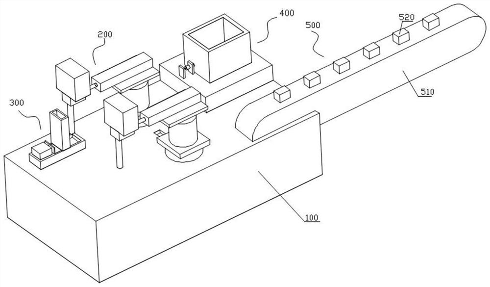
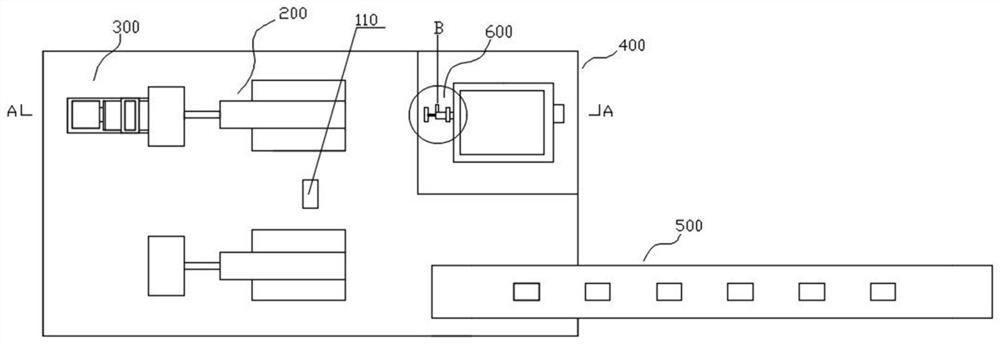
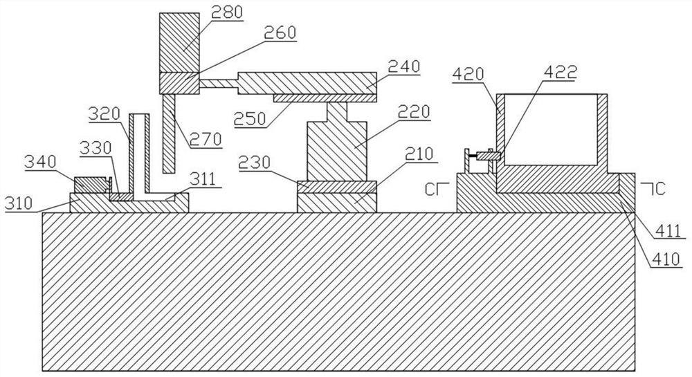
The invention relates to the technical field of laser bar detection, in particular to a laser bar test method and device, which comprises a base, a rotating cylinder, a first telescopic cylinder, a first mounting plate, a second telescopic cylinder, a second mounting plate, a third mounting plate, a suction nozzle and a negative pressure machine, the first installation plate is fixedly connected with the output end of the rotating air cylinder, the first telescopic air cylinder is longitudinally and fixedly installed above the first installation plate, the second installation plate is fixedly connected with the output end of the first telescopic air cylinder, the second telescopic air cylinder is transversely and fixedly installed on the second installation plate, and the third installation plate is fixedly connected with the output end of the second telescopic air cylinder. And the air suction nozzle is fixedly connected with the third mounting plate and is connected with an air inlet pipeline of the negative pressure machine, so that the work amount and the labor intensity of workers are reduced through the arrangement of the structure.

Description

technical field [0001] The invention relates to the technical field of laser bar detection, in particular to a method and equipment for laser bar detection. Background technique [0002] The laser bar is a single laser bar formed by multiple semiconductor single tubes side by side. It has many advantages such as high power conversion efficiency and small size. It is used in pumped solid-state lasers, fiber amplifiers, industry, laser medicine, optical storage, military and other fields good application prospects. [0003] In the production process of the laser bar, the laser bar needs to simulate the working state (a certain temperature and conductive state) to test its parameters after production. The laser bar is powered on to simulate the actual working situation, and it is tested with the help of testing equipment, such as spectrum testing instruments and current testing instruments. Due to the small size of the laser bar, it is difficult for the staff to work, and the ...

Claims


Application Information

Patent Timeline
Patent Type & Authority Applications(China)
IPC IPC(8): B07C5/02B07C5/344B07C5/34B07C5/36
CPCB07C5/02B07C5/344B07C5/34B07C5/362
Inventor 黄祥恩周永燊梁灵通
Owner 桂林芯隆科技有限公司
Learn More