Eureka AIR delivers breakthrough ideas for toughest innovation challenges, trusted by R&D personnel around the world.

Teaching robot moving device with anti-collision function

A teaching robot and mobile device technology, applied to teaching models, instruments, manipulators, etc., can solve problems such as teaching accidents, lack of educational resources, and easy collision of intelligent robotic arms with students, so as to ensure safety, prevent failure to avoid, and ensure teaching safe effect

Inactive Publication Date: 2022-05-27
江苏大石信息科技有限公司
View PDF0 Cites 0 Cited by
  • Summary
  • Abstract
  • Description
  • Claims
  • Application Information

AI Technical Summary

Problems solved by technology

[0004] Due to the lack of educational resources, when using automated robots for teaching, they are often used collectively by one or more classes. In this way, when many people are researching and studying around the equipment, the working intelligent robotic arm is likely to collide with the protruding heads of the students, causing teaching problems. accidents, so we highlight a teaching robot mobile device with anti-collision function to solve the problem

Method used


Image

  • Teaching robot moving device with anti-collision function
  • Teaching robot moving device with anti-collision function
  • Teaching robot moving device with anti-collision function

Examples


Embodiment 1

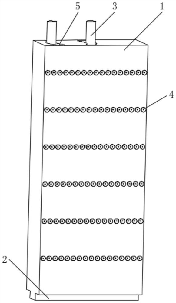
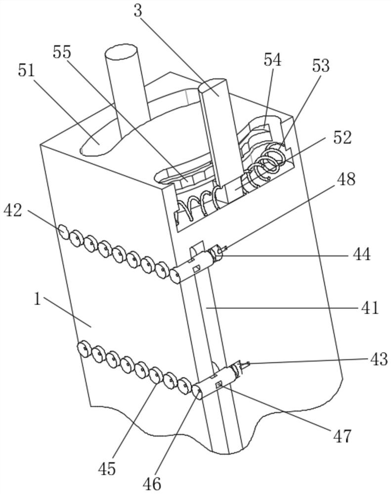
[0032] see Figure 1-2 , a teaching robot mobile device with anti-collision function, including a mechanical arm 1, the bottom of the mechanical arm 1 is fixedly connected to the clamping piece installation port 2, the top of the mechanical arm 1 is installed with a power rod 3, there are two power rods 3, one The root is located at the center of the top of the robotic arm 1, and the other is located on the side of the top of the robotic arm 1. The power rod 3 is divided into two upper and lower sections, and the two sections are connected by bearings;

[0033] A sensing mechanism 4 for predicting collision is arranged on the outer surface of the robotic arm 1 that is perpendicular to its own running track;

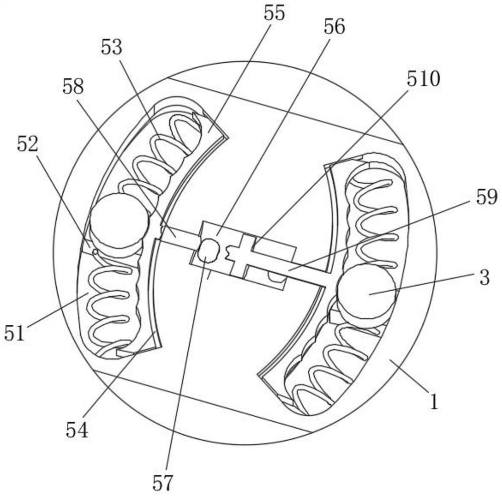
[0034] An avoidance mechanism 5 that reduces the impact of collision is installed between the robot arm 1 and the power rod 3 .

[0035] The induction mechanism 4 includes an air cavity 41 opened on the inner side of the mechanical arm 1;

[0036] The induction mechanis...

Embodiment 2

[0044] see Figure 1-2 , a teaching robot mobile device with anti-collision function, including a mechanical arm 1, the bottom of the mechanical arm 1 is fixedly connected to the clamping piece installation port 2, the top of the mechanical arm 1 is installed with a power rod 3, there are two power rods 3, one The root is located at the center of the top of the robotic arm 1, and the other is located on the side of the top of the robotic arm 1. The power rod 3 is divided into two upper and lower sections, and the two sections are connected by bearings;

[0045] A sensing mechanism 4 for predicting collision is arranged on the outer surface of the robotic arm 1 that is perpendicular to its own running track;

[0046] An avoidance mechanism 5 that reduces the impact of collision is installed between the robot arm 1 and the power rod 3 .

[0047] The induction mechanism 4 includes an air cavity 41 opened on the inner side of the mechanical arm 1;

[0048] The induction mechanis...

Embodiment 3

[0058] see Figure 1-3 , a teaching robot mobile device with anti-collision function, including a mechanical arm 1, the bottom of the mechanical arm 1 is fixedly connected to the clamping piece installation port 2, the top of the mechanical arm 1 is installed with a power rod 3, there are two power rods 3, one The root is located at the center of the top of the robotic arm 1, and the other is located on the side of the top of the robotic arm 1. The power rod 3 is divided into two upper and lower sections, and the two sections are connected by bearings;

[0059] A sensing mechanism 4 for predicting collision is arranged on the outer surface of the robotic arm 1 that is perpendicular to its own running track;

[0060] An avoidance mechanism 5 that reduces the impact of collision is installed between the robot arm 1 and the power rod 3 .

[0061] The induction mechanism 4 includes an air cavity 41 opened on the inner side of the mechanical arm 1;

[0062] The induction mechanis...


PUM


Abstract

The teaching robot moving device with the anti-collision function comprises a mechanical arm, the bottom of the mechanical arm is fixedly connected with a clamping piece installation opening, two power rods are installed on the top of the mechanical arm, one power rod is located in the center of the top of the mechanical arm, and the other power rod is located on the side face of the top of the mechanical arm. The power rod is divided into an upper section and a lower section which are connected through a bearing; an induction mechanism for predicting collision is arranged on the outer surface, perpendicular to the moving track of the mechanical arm, of the mechanical arm. According to the teaching robot moving device with the anti-collision function, the air cylinder is arranged on the surface of the mechanical arm, when the mechanical arm runs, air flows out of the air blowing hole, when the mechanical arm encounters a shielding object, the air blown out of the air blowing hole rebounds, the air cylinder is pushed to move backwards, in this way, the opening diameter of the air inlet hole is increased, and the air flow of air outlet is also increased; therefore, a prompting effect is achieved, the sheltered person can avoid, the safety of students is guaranteed, and the operation of equipment is not affected.

Description

technical field [0001] The invention relates to the technical field of automated robots, in particular to a teaching robot mobile device with an anti-collision function. Background technique [0002] With the emphasis on education, my country's investment in education is increasing every year. In science and technology colleges, the role of practical teaching is far greater than theoretical teaching. Therefore, major universities are actively introducing advanced practical teaching equipment, such as CNC lathes, PLC control equipment, automated robots, etc. [0003] The automated robot is specifically a set of simplified automated production lines controlled by intelligent robots. [0004] Due to the lack of educational resources, when using automated robots for teaching, it is often used collectively by one or more classes. In this way, when many people are studying and studying around the equipment, the working intelligent robotic arm is easy to collide with the protruding...

Claims


Application Information

Patent Timeline
Patent Type & Authority Applications(China)
IPC IPC(8): B25J19/00B25J18/00B25J11/00G09B25/02
CPCB25J19/00B25J18/00B25J11/00G09B25/02
Inventor 张怀远
Owner 江苏大石信息科技有限公司
Why Eureka
Eureka Blog
Learn More