Eureka AIR delivers breakthrough ideas for toughest innovation challenges, trusted by R&D personnel around the world.

Cable pay-off device

A pay-off device and cable technology, which is applied in the directions of transportation and packaging, thin material handling, and delivery of filamentous materials, etc., can solve the inconvenient overall transfer and mobile pay-off, the left and right positions of the reel are not fixed, and the shaft rod Mutual wear and other problems, to achieve the effect of eliminating relative rotation sliding and left and right movement, saving manpower and convenient loading

Pending Publication Date: 2022-05-27
HUBEI XISAISHAN POWER GENERATION CO LTD
View PDF0 Cites 0 Cited by
  • Summary
  • Abstract
  • Description
  • Claims
  • Application Information

AI Technical Summary

Problems solved by technology

[0005] ①Split bracket design, inconvenient for overall transfer and mobile pay-off
[0007] ③ There is relative sliding and mutual wear between the shaft rod and the cable reel, which is prone to vibration
[0008] ④The left and right positions of the reel are not fixed. When the reel rotates and pays off the wire, the reel tends to move left and right on the shaft rod and rub against the bracket.
Especially when the ground is not flat enough, there is a height difference between the two supports, and it is more likely to happen when the shaft is tilted.

Method used


Image

  • Cable pay-off device
  • Cable pay-off device
  • Cable pay-off device

Examples


Embodiment Construction

[0043] The present invention is further described below in conjunction with the accompanying drawings and embodiments.

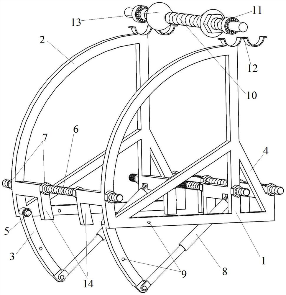
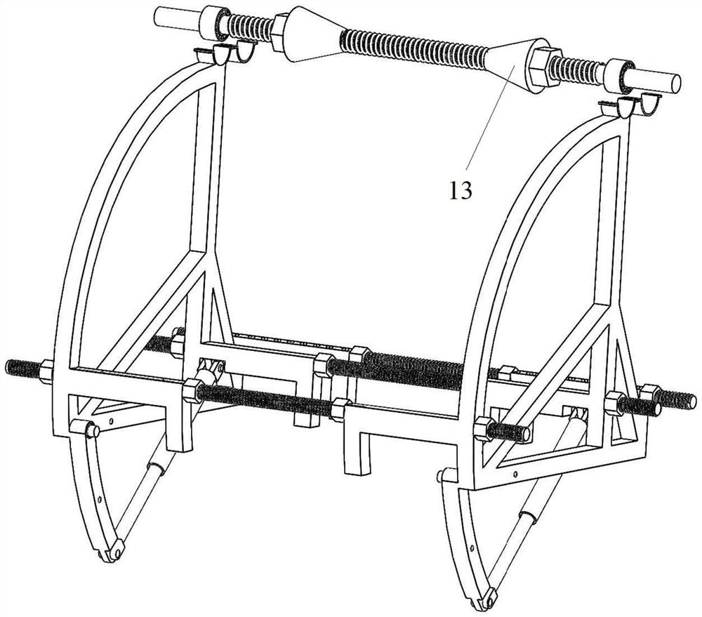
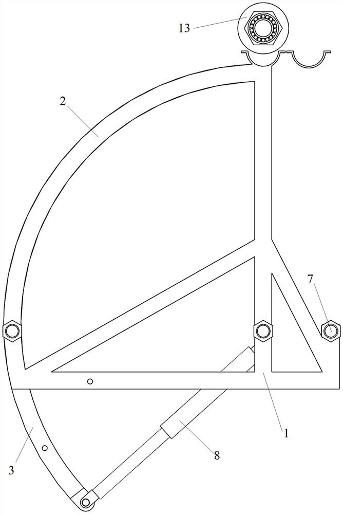
[0044] In the present embodiment, a cable release device such as Figures 1 to 3 As shown, include at least two brackets. In the present embodiment, the bracket comprises a support rod 1, an arc long arm 2 and a circular short arm 3. Among them, the support rod is inverted "T" shape, the arc long arm is fixed and connected to the top of the support rod and the bottom end, and the arc of the arc long arm is 90 °, that is, the arc long arm and part of the support rod form a right-angle fan structure. Both ends of the bottom of the support rod and the middle of the support rod are fixed by the diagonal strut 4.

[0045] One end of the arc short arm and the bottom of the arc long arm are connected by the rotation axis 5 activity, so that the other end of the arc short arm rotates around the arc long arm in the vertical straight plane, and the radius of the arc short ...


PUM


Abstract

The invention provides a cable pay-off device which comprises a rotating shaft rod and a support, the rotating shaft rod is fixed to the top of the support through a bearing, and the support comprises a supporting rod, an arc long arm and an arc short arm; the arc long arm is fixedly connected to one end of the top end and one end of the bottom of the supporting rod, one end of the arc short arm is movably connected with the bottom of the arc long arm, the other end of the arc short arm rotates in a vertical plane around the arc long arm, and the radius of the arc short arm is equal to that of the arc long arm; threaded rods are distributed and connected to the positions, close to the bottoms of the supporting rods, between the two supports, the other ends of the arc short arms are connected to the threaded rods through damping spring air cylinders, and when the damping spring air cylinders are not subjected to external force, the arc short arms and the arc long arms form continuous arcs. The arc short arm slowly retracts to be flush with the bottom of the supporting rod along with the damping spring air cylinder. The device can adapt to impact-free loading of different cable reels and can also be used for lifting cable cover plates.

Description

Technical field [0001] The present invention relates to the technical field of power cable handling, specifically to a cable release device. Background [0002] Power cables are very heavy, and it is cumbersome to release the cables from the cable reels when laying the cables. At present, there are two main methods of release: [0003] (1) Ground rolling line release method, that is, the cable reel is placed on the ground to roll and a section of the cable is pulled out. This method is the most primitive, labor-intensive, and time-consuming way to put the line, but it does not require additional auxiliary tools and can still be seen on the construction site. In addition, since the diameter of the support wheel of the reel is larger than the diameter at the cable, and the fewer cables remaining in the coil, the greater the diameter difference between the two. This makes the reel roll at an angle when the cable is placed, and the support wheel of the reel rolls on the ground corres...

Claims


Application Information

Patent Timeline
Patent Type & Authority Applications(China)
IPC IPC(8): B65H49/32
CPCB65H49/324B65H49/321B65H2701/34
Inventor 王亚洲
Owner HUBEI XISAISHAN POWER GENERATION CO LTD
Why Eureka
Eureka Blog
Learn More