Concrete column and steel beam connecting structure

A technology for concrete columns and connecting structures, which is applied in truss structures, columns, joists, etc., can solve the problems of poor connection between steel beams and concrete, low connection structure strength, complicated construction process, etc., and achieves high overall connection structure strength. , Reduce the construction process and improve the effect of shear resistance

Pending Publication Date: 2022-05-27
上海民航新时代机场设计研究院有限公司
View PDF0 Cites 0 Cited by
  • Summary
  • Abstract
  • Description
  • Claims
  • Application Information

AI Technical Summary

Problems solved by technology

[0005] In view of the shortcomings of the prior art described above, the purpose of the present invention is to provide a connection structure between concrete columns and steel beams, which is used to solve the problem of complex construction technology and difficult construction in the existing connection structures of concrete columns and steel beams in the prior art. , the connection between the steel beam and the concrete is not tight, and the strength of the connection structure is low

Method used


Image

  • Concrete column and steel beam connecting structure
  • Concrete column and steel beam connecting structure
  • Concrete column and steel beam connecting structure

Examples


Embodiment 1

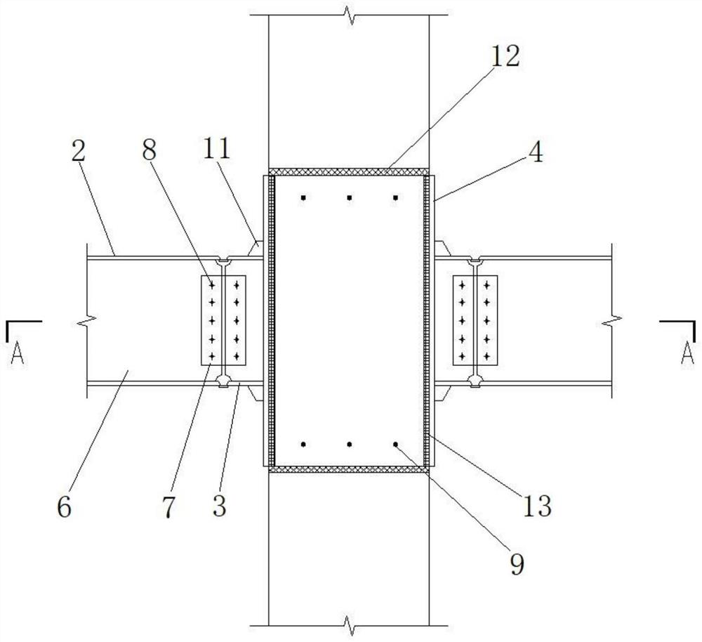
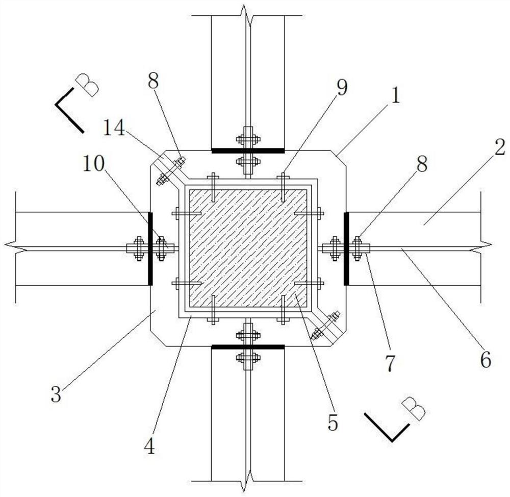
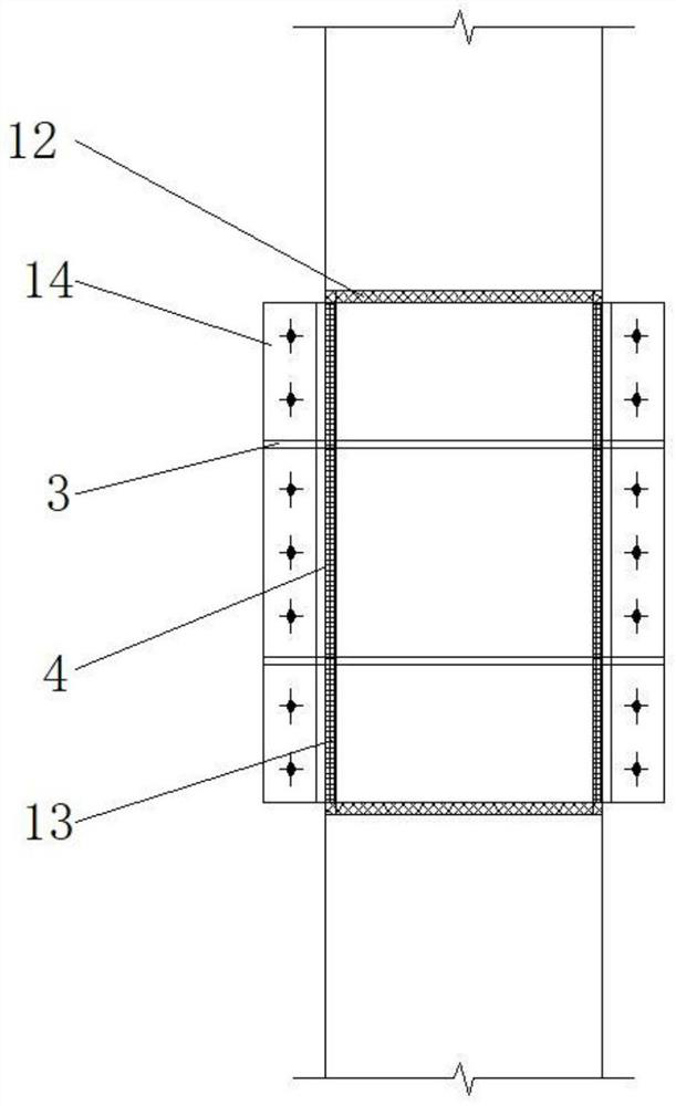
[0034] see Figure 1 to Figure 3 , the present invention provides a concrete column and steel beam connection structure, including a concrete column 5, a connection mechanism 1 and a steel beam 2, the concrete column 5 is square, the connection mechanism 1 is set outside the concrete column 5, the steel beam 2 and the connection mechanism 1. Fixed connection, the connection mechanism 1 includes two connecting end plates 4 symmetrically wrapped on the outside of the concrete column 5, and several anchor bolts 9 are evenly spaced between the upper and lower ends of the connecting end plate 4 and the concrete column 5, and the connecting end plates 4 It is L-shaped, and an assembled rib 14 extends outward from the joint of the two connecting end plates 4. The assembled rib 14 at the joint of the two connecting end plates 4 is fixedly connected by connecting bolts 8, and the connecting end plate 4 and the concrete column 5 are connected. There is a gap between the upper and lower ...

Embodiment 2

[0036] see Figure 4 to Figure 6, the present invention provides a concrete column and steel beam connection structure, including a concrete column 5, a connection mechanism 1 and a steel beam 2, the concrete column 5 is square, the connection mechanism 1 is set on the outer surface of the concrete column 5, and the steel beam 2 is connected with The mechanism 1 is fixedly connected, and the connection mechanism 1 includes two connecting end plates 4 symmetrically covered on the outer surface of the concrete column 5. Several anchor bolts 9 are evenly spaced between the upper and lower ends of the connecting end plate 4 and the concrete column 5. The plate 4 is semi-circular, and there are assembled rib plates 14 extending outward from the joints of the two connecting end plates 4. The assembled rib plates 14 at the joints of the two connecting end plates 4 are fixedly connected by connecting bolts 8, and the connecting end plates 4 are connected with the concrete. There is a ...


PUM


Abstract

The invention provides a concrete column and steel beam connecting structure, and belongs to the technical field of building structures. The connecting structure comprises a concrete column, a connecting mechanism and a steel beam, the connecting mechanism sleeves the outer side of the concrete column, the steel beam is fixedly connected with the connecting mechanism, the connecting mechanism comprises two connecting end plates symmetrically wrapping the outer side of the concrete column, a gap exists between the connecting end plates and the concrete column, and a grouting layer is poured in the gap; two outer ring plates are vertically and symmetrically arranged on the outer side surface of the connecting end plate, connecting rib plates are evenly arranged between the two outer ring plates at intervals, a steel beam web in the steel beam is fixedly connected with the connecting rib plates through connecting plates, and the connecting plates are fixedly connected with the steel beam web and the connecting rib plates through connecting bolts. The structural strength of connection of the steel beam and the concrete column is effectively improved.

Description

technical field [0001] The invention relates to a connection structure between a concrete column and a steel beam, and belongs to the technical field of building structures. Background technique [0002] The frame node is the key to connect the frame beam and the frame column, and the connection node should have sufficient bearing capacity, stiffness and ductility. In the reconstruction and expansion project of the existing reinforced concrete frame structure, the new part adopts the steel structure scheme, which has many advantages such as small load increase, avoidance of wet work, and fast construction speed. Therefore, it is of great significance to study the connection structure and construction technology of suitable new steel beams and existing reinforced concrete columns. [0003] At present, the existing connection structure between the newly added steel beam and the reinforced concrete column mainly adopts the end plate, and the end plate is connected with the con...

Claims


Application Information

Patent Timeline
Patent Type & Authority Applications(China)
IPC IPC(8): E04B1/58E04C3/04E04C3/34
CPCE04B1/5812E04B1/5831E04C3/04E04C3/34E04B2001/5875
Inventor 金怀印王福龙熊宏钧蒋锋平
Owner 上海民航新时代机场设计研究院有限公司
Why Eureka
Try Eureka