Contact wear resistance testing tool
A technology for wear resistance and testing tooling, applied in the direction of testing wear resistance, measuring device, strength characteristics, etc., can solve the problems of high cost, time-consuming and laborious, high resistivity, and achieve simple structure, low test cost, and easy setting. Effect
- Summary
- Abstract
- Description
- Claims
- Application Information
AI Technical Summary
Problems solved by technology
Method used
Image

Examples
specific Embodiment 1
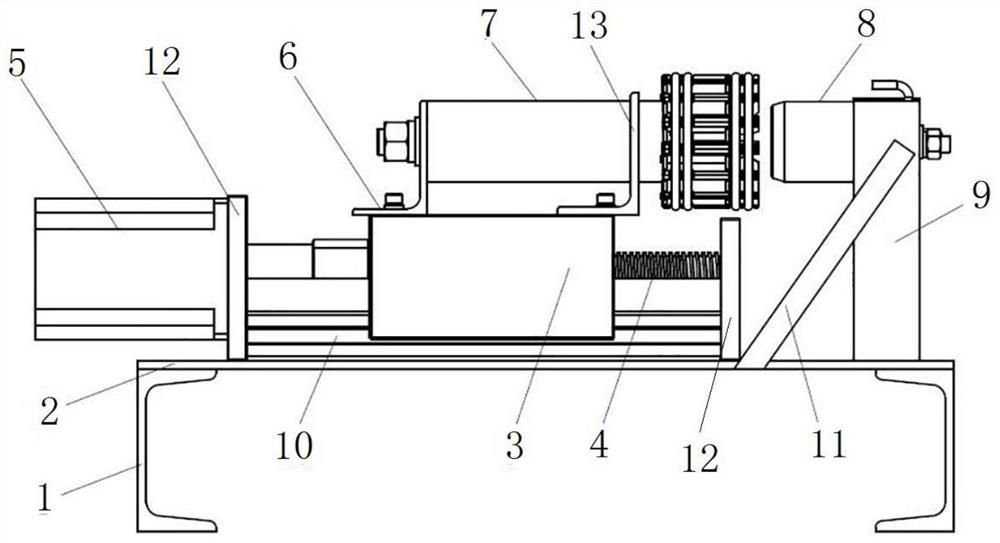
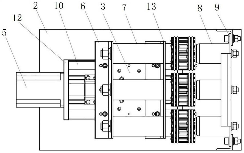
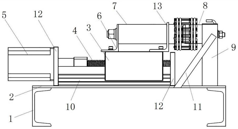
[0040] like Figure 1 to Figure 3 As shown, the contact wear resistance test tool includes a frame, the frame includes a channel steel 1 and a bottom plate 2 fixed on the channel steel 1, there are two channel steels 1, the two channel steels 1 are arranged in parallel, and the bottom plate 2 is welded on On channel steel 1. The bottom plate 2 of the frame is fixed with a static contact fixing piece, the static contact fixing piece is used to fix the static contact 8, the static contact fixing piece is a fixing plate 9, the fixing plate 9 is welded on the base plate 2, and the static contact 8 The installation method on the fixed plate 9 is the same as the installation method of the static contact 8 on the actual circuit breaker. In this embodiment, the static contact 8 is installed on the fixed plate 9 by bolts. In other implementations, the fixing plate 9 can also be connected with the bottom plate 2 by bolts.
[0041] In this embodiment, as figure 2 As shown, the contac...
specific Embodiment 2
[0051] The difference from the specific embodiment 1 is that: there is no linear transmission mechanism in the driving mechanism, the driving mechanism includes a telescopic cylinder, the telescopic cylinder is a hydraulic cylinder, the hydraulic cylinder is fixed on the bottom plate of the frame, and the sliding table is directly fixed with the output end of the hydraulic cylinder. Connected, under the driving action of the hydraulic cylinder, the sliding table reciprocates linearly along the guide rail.
[0052] In other embodiments, the drive mechanism is not provided with a linear transmission mechanism, the telescopic cylinder can also be an air cylinder, the air cylinder is fixed on the bottom plate of the frame, and the sliding table is fixedly connected with the output end of the air cylinder. The guide rail moves linearly back and forth.
specific Embodiment 3
[0054] The difference from the specific embodiment 1 is that no guide rails are provided on the rack, the sliding table is threadedly connected with the lead screw, and the lower surface of the sliding table is in contact with the upper surface of the bottom plate. The extension direction drives the moving contact to reciprocate, and the sliding table and the bottom plate fit together to prevent the sliding table from skewing or shaking in the process of linear reciprocating movement with the lead screw.
PUM
 Abstract
Description
Claims
Application Information