Supercharge Your Innovation With Domain-Expert AI Agents!

Local anesthesia auxiliary monitoring equipment for clinical anesthesiology department

A technology of local anesthesia and monitoring equipment, which is applied in the direction of mechanical equipment, machines/brackets, supporting machines, etc. It can solve the problems that cannot be processed in time, cannot observe the basic situation of patients, and has a wide viewing angle area, so as to avoid the problems that cannot be processed in time Emergencies, easy to observe, easy to fix the effect

Inactive Publication Date: 2022-05-31
滕州市中心人民医院
View PDF0 Cites 0 Cited by
  • Summary
  • Abstract
  • Description
  • Claims
  • Application Information

AI Technical Summary

Problems solved by technology

However, the existing video monitoring equipment is basically installed on the wall of the inner room, and its viewing angle is wide, so it is impossible to observe the basic situation of the patient, especially the patient under local anesthesia, which will lead to inability to timely deal with the occurrence of

Method used


Image

  • Local anesthesia auxiliary monitoring equipment for clinical anesthesiology department
  • Local anesthesia auxiliary monitoring equipment for clinical anesthesiology department

Examples


Embodiment 1

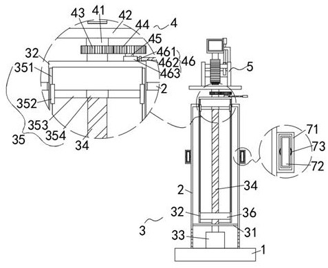
[0019] as Figure 1-2As shown, a clinical anesthesiology department proposed in the present invention with local anesthesia auxiliary monitoring apparatus, comprising a base 1, the upper end of the base 1 is fixed with a hollow column a2, the upper end of the hollow column A2 is provided with a camera 6, the hollow column a2 is provided with a lifting mechanism 3 for lifting and lowering the camera 6, the lifting mechanism 3 includes a partition 31 fixed in the hollow column a2, the upper side of the partition 31 is provided with a hollow column b32, and the upper end of the hollow column B32 extends to the upper side of the hollow column a2, and the lower part of the partition 31 is provided with a drive motor 33, The output end of the drive motor 33 extends to the hollow column b32 and is fixed with a lead screw 34, the upper part of the screw 34 is provided with a guide assembly 35, the screw 34 is screwed with a thread sleeve 36, and the outer wall of the thread sleeve 36 is fi...

Embodiment 2

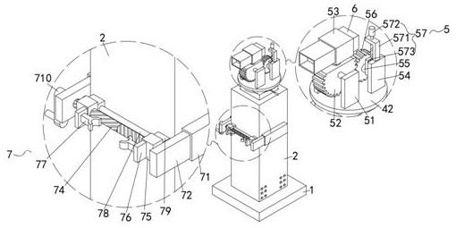
[0023] as Figure 1 and Figure 2 As shown, the present invention proposes a clinical anesthesiology department with local anesthesia auxiliary monitoring apparatus, compared to Example I, the present embodiment further comprises: the clamping mechanism 7 includes a hollow column a2 left and right sides of the wall are fixed mounted mounting box 71, the inner bottom end of the mounting box 71 is fixed with a spring 73, the front end of the spring 73 is fixed with an extension plate 72, and the front end of the extension plate 72 extends to the front side of the mounting box 71, the rotation between the two extension plates 72 is connected to a bi-directional screw 74, and the left end of the two-way screw 74 extends to the outside of the extension plate 72 , the two-way screw 74 is screwed with a threaded sleeve 75 at both ends, the front end of the thread sleeve 75 is fixed with a positioning plate 76, the two positioning plates 76 are fixed to one side wall of each other 77, and t...


PUM


Abstract

The invention relates to the technical field of monitoring equipment, in particular to local anesthesia auxiliary monitoring equipment for a clinical anesthesiology department. According to the technical scheme, the device comprises a base, a hollow column a is fixed to the upper end of the base, a camera is arranged above the hollow column a, a lifting mechanism for lifting the camera is arranged in the hollow column a, and a rotating mechanism a and a rotating mechanism b for adjusting the angle of the camera are arranged above the lifting mechanism; and a clamping mechanism for positioning the hollow column a is arranged on the hollow column a. By improving the monitoring equipment, the monitoring equipment has the functions of adjusting the height and the angle, facilitating fixation and the like, so that a patient can be effectively and conveniently observed, and the situation that emergencies cannot be handled in time is avoided.

Description

Technical field [0001] The present invention relates to the technical field of monitoring equipment, in particular to a clinical anesthesiology department with local anesthesia auxiliary monitoring device. Background [0002] Local anesthesia requires observation of the patient in order to understand the patient's condition. Observation is usually carried out in a combination of video surveillance equipment and inspection. However, the existing video surveillance equipment is basically installed in the inner chamber wall, its viewing angle is wide, can not observe the basic situation of the patient, especially the patient with local anesthesia, in the face of emergencies, will lead to the inability to deal with the situation in time. Contents of the Invention [0003] Object of the present invention is to propose a convenient clinical anesthesiology with local anesthesia auxiliary monitoring device in response to problems in the background technique. [0004] Technical solution ...

Claims


Application Information

Patent Timeline
Patent Type & Authority Applications(China)
IPC IPC(8): F16M11/28F16M11/12F16M11/18F16M11/04
CPCF16M11/28F16M11/12F16M11/18F16M11/04
Inventor 陶宏龙霞
Owner 滕州市中心人民医院
Features
  • R&D
  • Intellectual Property
  • Life Sciences
  • Materials
  • Tech Scout
  • Unparalleled Data Quality
  • Higher Quality Content
  • 60% Fewer Hallucinations
Learn More