Performance test method and device for flexible touch screen
A technology of flexible touch and testing equipment, which is applied in the application of repetitive force/pulse force to test the strength of materials, reduce energy consumption, and measure devices, etc. The control screen test equipment has a single test direction and other problems, so as to avoid damage.
- Summary
- Abstract
- Description
- Claims
- Application Information
AI Technical Summary
Problems solved by technology
Method used
Image

Examples
Embodiment 1
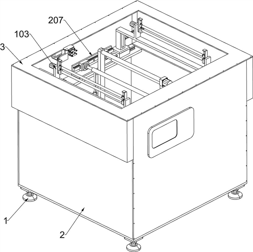
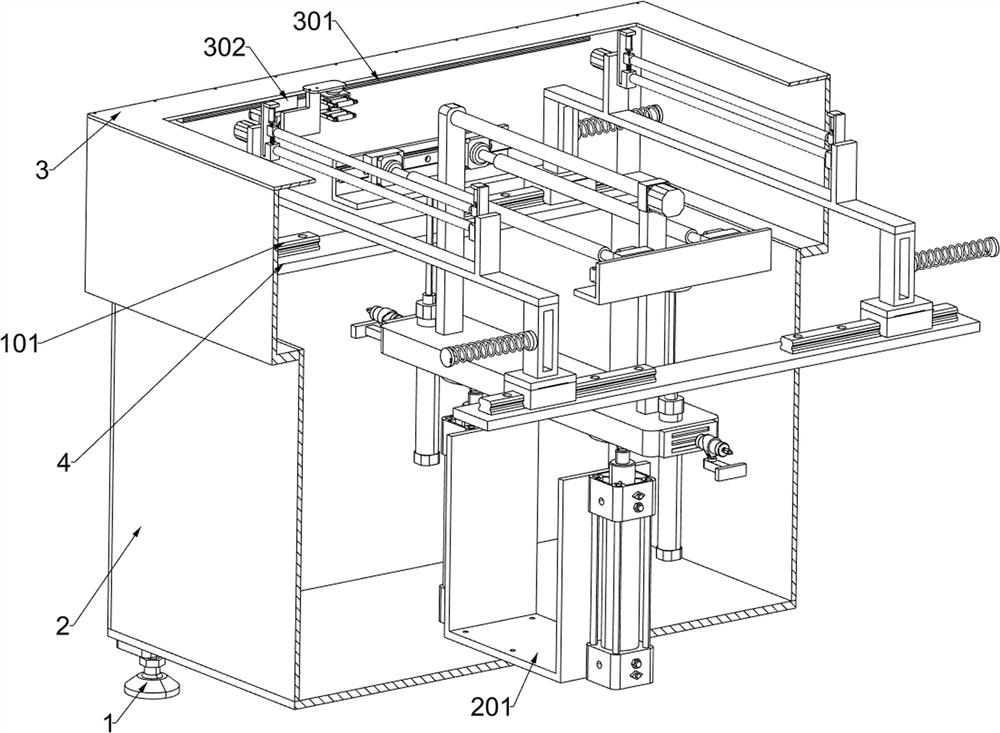
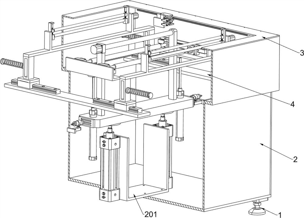
[0042] A performance testing device for a flexible touch screen, such as Figure 1-3 As shown, it includes a mounting base 1, a frame 2, a top cover 3, a mounting plate 4, a positioning installation system and a performance testing system; the four mounting bases 1 are fixed on the surface of the frame 2; The top cover 3; the internal front side and the internal rear side of the frame 2 are respectively fixed with a mounting plate 4; the upper surfaces of the two mounting plates 4 are connected with a positioning installation system for clamping the flexible touch screen and realizing the rotation of the edge of the screen; A performance testing system is connected to the inner bottom surface of the frame 2 .
[0043] Before using the performance testing equipment of the flexible touch screen, the heights of the four mounts 1 are adjusted accurately, and then the staff powers on the performance testing equipment of the flexible touch screen, and manually or mechanically assist...
Embodiment 2
[0045] On the basis of Example 1, such as figure 1 , Figure 4 and Figure 5 As shown, the positioning installation system includes a straight slide rail 101, a moving block 102, a fixed frame 103, a first elastic member 104, a first servo motor 105, a first support frame 106, a receiving rod 107, a first electric telescopic member 108, The support block 109, the pressure rod 1010 and the second elastic member 1011; the upper surface of the mounting plate 4 in the front and the mounting plate 4 in the rear are respectively fixed with two straight slide rails 101; each of the four straight slide rails 101 is slidably connected with a The moving block 102; the opposite sides of the left and right adjacent moving blocks 102 are respectively fixed with a first elastic member 104; the four first elastic members 104 are all fixed to the frame 2; the front and rear adjacent moving blocks 102 are fixed on the upper surface There is a fixed frame 103; a first servo motor 105 is fixed...
Embodiment 3
[0055] On the basis of Example 2, such as figure 1 and Figure 8-10 As shown, it also includes an upright system; the rear part of the lower surface of the mounting plate 4 is connected with an upright system; Part 304, connecting plate 305, fixed plate 306, electric turntable 307, second support frame 308, first circular lever 309, micro motor 3010, fourth electric telescopic member 3011, third support frame 3012 and second circular The lever 3013; the rear part of the lower surface of the mounting plate 4 is bolt-connected with the second electric slide rail 301; the second electric slide rail 301 is slidingly connected with the third electric slide block 302; the bottom of the third electric slide block 302 is fixedly connected with a fixed block 303; the third electric telescopic part 304 is fixedly connected to the fixed block 303; the telescopic part of the third electric telescopic part 304 is fixedly connected with the connecting plate 305; the upper part of the conne...
PUM
 Abstract
Description
Claims
Application Information
 - R&D Engineer
- R&D Manager
- IP Professional
- Industry Leading Data Capabilities
- Powerful AI technology
- Patent DNA Extraction
Browse by: Latest US Patents, China's latest patents, Technical Efficacy Thesaurus, Application Domain, Technology Topic.
© 2024 PatSnap. All rights reserved.Legal|Privacy policy|Modern Slavery Act Transparency Statement|Sitemap