Method and device for detecting surface defects of optical element and electronic equipment

A technology of optical components and detection methods, applied in the field of optical detection, can solve problems that affect the quality of optical components, affect the production and manufacture of optical products, and achieve the effect of improving accuracy

Pending Publication Date: 2022-05-31
GOERTEK OPTICAL TECH CO LTD
View PDF0 Cites 3 Cited by
  • Summary
  • Abstract
  • Description
  • Claims
  • Application Information

AI Technical Summary

Problems solved by technology

Defects such as the above defects and pollutants seriously affect the quality of optical components, which in turn affects the production and manufacture of optical products

Method used


Image

  • Method and device for detecting surface defects of optical element and electronic equipment
  • Method and device for detecting surface defects of optical element and electronic equipment
  • Method and device for detecting surface defects of optical element and electronic equipment

Examples


Embodiment Construction

[0033] Various exemplary embodiments of the present application will now be described in detail with reference to the accompanying drawings. It should be noted that the relative arrangements of components and steps, numerical expressions and numerical values ​​set forth in these embodiments do not limit the scope of the present application unless specifically stated otherwise.

[0034] The following description of at least one exemplary embodiment is merely illustrative in nature and in no way serves as any limitation of the application, its application or uses.

[0035] Techniques, methods and devices known to those of ordinary skill in the relevant art may not be discussed in detail, but where appropriate, such techniques, methods and devices should be considered part of the description.

[0036] In all examples shown and discussed herein, any specific values ​​should be construed as exemplary only, and not as limitations. Therefore, other instances of the exemplary embodim...


PUM


Abstract

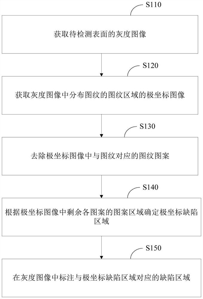
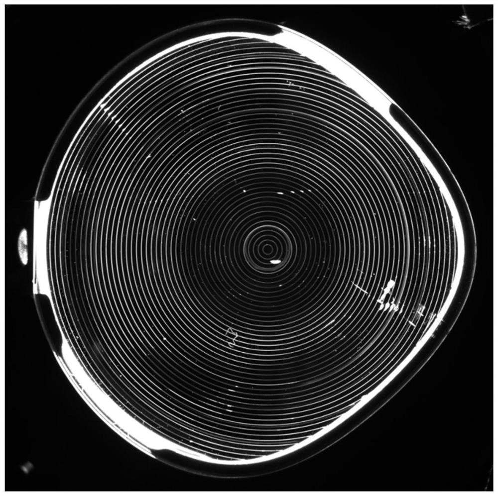
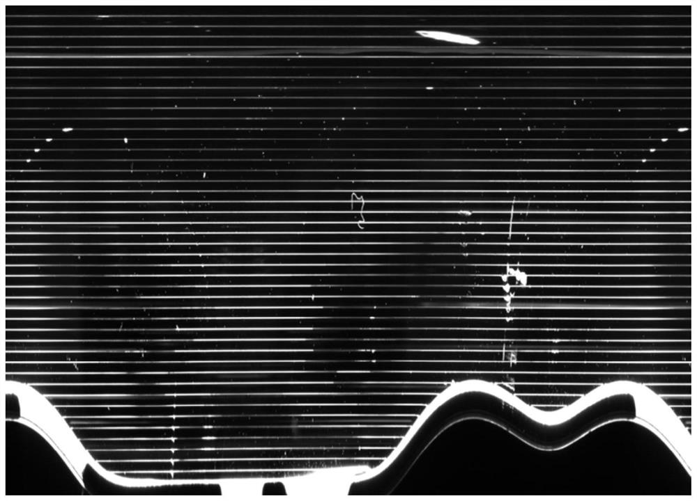
The invention relates to an optical element surface defect detection method and device, electronic equipment and a computer readable storage medium, and relates to the technical field of optical detection. Fresnel patterns are etched on the to-be-detected surface of the optical element. The method comprises the following steps: acquiring a grayscale image of the to-be-detected surface; obtaining a polar coordinate image of a target area where Fresnel fringes are distributed in the grayscale image; removing a Fresnel pattern corresponding to the Fresnel pattern in the polar coordinate image; determining a polar coordinate defect area according to the pattern area of each remaining pattern in the polar coordinate image; and marking a defect area corresponding to the polar coordinate defect area in the grayscale image.

Description

technical field [0001] The present application relates to the technical field of optical detection, and more specifically, to a detection method, device, electronic equipment, and computer-readable storage medium for detecting surface defects of optical components. Background technique [0002] In the production process of optical components such as lenses, defects (such as scratches, pits, etc.) or contamination will inevitably appear on the surface of the optical components. Defects such as the above defects and pollutants seriously affect the quality of optical components, and further affect the production and manufacture of optical products. Based on the above situation, at present, the surface of the optical element is inspected by manual inspection or computer automatic inspection, so as to find out the defects on the surface of the optical element, so as to effectively evaluate the quality of the optical element. [0003] Compared with manual detection, automatic det...

Claims


Application Information

Patent Timeline
Patent Type & Authority Applications(China)
IPC IPC(8): G06T7/00G06T3/40G06T5/30
CPCG06T7/0004G06T3/4007G06T5/30
Inventor 崔世君王建成胥洁浩金玲赵俊瑞韩雪
Owner GOERTEK OPTICAL TECH CO LTD
Why Eureka
Try Eureka