
Monomer direct-current-component-resistant magnetic core production process and equipment

A kind of production equipment and anti-DC technology, which is applied in the direction of magnetic core manufacturing, inductor/transformer/magnet manufacturing, electrical components, etc., can solve the problems of inconvenient milling slots, etc., and achieve the effect of improving applicability and scope of application

Inactive Publication Date: 2022-06-03
徐州奥纳富霖电子科技有限公司
View PDF0 Cites 0 Cited by
  • Summary
  • Abstract
  • Description
  • Claims
  • Application Information

AI Technical Summary

Problems solved by technology

[0005] In order to overcome the above-mentioned defects of the prior art, the embodiment of the present invention provides a single anti-DC component magnetic core production process and equipment. The problem to be solved by the present invention is: the existing magnetic core production and processing equipment is not easy to change the magnetic core Milling slots on both sides

Method used


Image

  • Monomer direct-current-component-resistant magnetic core production process and equipment
  • Monomer direct-current-component-resistant magnetic core production process and equipment
  • Monomer direct-current-component-resistant magnetic core production process and equipment

Examples


Embodiment

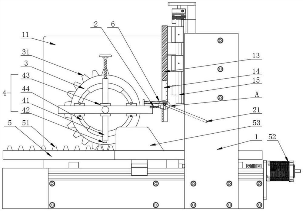
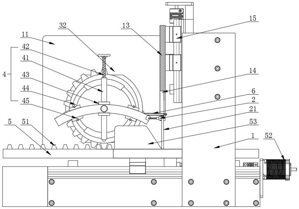
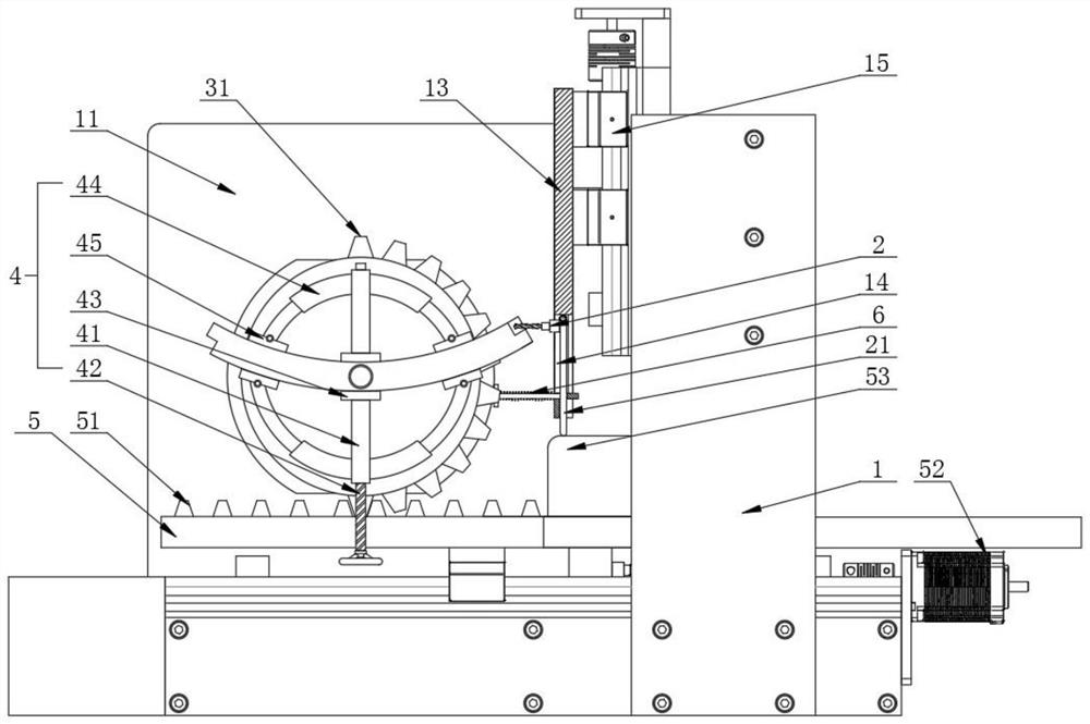
[0044] Refer to the manual attached Figure 1-Figure 12 , a single anti-DC component magnetic core production equipment, including a frame 1, the frame 1 is composed of a base and a gantry, side plates 11 are installed on both sides of the base, and the inner wall of the side plate 11 is provided with a clamp assembly 4, The gantry is provided with a cutter assembly 2, the cutter assembly 2 includes a milling cutter and a fixed seat, the milling cutter is rotatably installed on the fixed seat, the first driving part is installed on the side of the fixed seat away from the milling cutter, and the first driving part is The output end is fixedly connected with the milling cutter, the first driving member drives the milling cutter to rotate at high speed, the first driving member can be a motor or a motor, the milling cutter driving device 12 drives the fixed seat to move laterally, and the milling cutter driving device 12 can be a screw drive device or cylinder drive;

[0045] T...


PUM


Abstract

The invention discloses a process and equipment for producing a single direct-current component resistant magnetic core, and particularly relates to the field of magnetic core production.The equipment comprises a rack, side plates are installed on the two sides of the rack, clamp assemblies are arranged on the inner walls of the side plates, a cutter assembly is arranged in the rack, the cutter assembly comprises a milling cutter and a fixing base, and the milling cutter is installed on the fixing base; the milling cutter rotates at a high speed through a first driving part, the milling cutter driving device drives the fixing base to move transversely, the inner wall of the side plate is rotationally connected with a rotating plate, a half circle of gear teeth are integrally formed on the outer side of the rotating plate, and the clamp assembly comprises two sleeves which are symmetrically arranged. The driving device drives the transverse plate to transversely move, the first plate teeth are meshed with the gear teeth, the clamp assembly is driven to turn over by 180 degrees, the magnetic core workpiece is driven to rotate for edge changing, the position changing function that the machining equipment drives the workpiece to turn over by 180 degrees through the clamping assembly is achieved, and the function of milling grooves in the two side edges of the flat plate workpiece at a time is achieved.

Description

technical field [0001] The invention relates to the technical field of magnetic core production, and more particularly, the invention relates to a production process and equipment for a single anti-DC component magnetic core. Background technique [0002] Magnetic core refers to a sintered magnetic metal oxide composed of various iron oxide mixtures. For example, manganese-zinc ferrite and nickel-zinc ferrite are typical magnetic core materials. Manganese-zinc ferrites are characterized by high magnetic permeability and high magnetic flux density with low loss characteristics. Nickel-zinc ferrites have extremely high resistivity and low magnetic permeability of less than a few hundred. Ferrite cores are used in coils and transformers of various electronic devices. [0003] There are two types of single anti-DC component magnetic cores: one-piece and split-type. The split-type magnetic core is generally composed of two or more arc-shaped lobed magnetic cores, and the adjac...

Claims


Application Information

Patent Timeline
Patent Type & Authority Applications(China)
IPC IPC(8): H01F41/02
CPCH01F41/0206
Inventor 李伟
Owner 徐州奥纳富霖电子科技有限公司
Learn More