Ultrasonic detector for pipeline flaw detection

An ultrasonic and detector technology, applied in the analysis of solids using sonic/ultrasonic/infrasonic waves, material analysis using sonic/ultrasonic/infrasonic waves, instruments, etc., to achieve the effect of improving the effect, improving efficiency and enhancing stability

Inactive Publication Date: 2022-06-10
南京力聚工程检测有限公司
View PDF0 Cites 0 Cited by
  • Summary
  • Abstract
  • Description
  • Claims
  • Application Information

AI Technical Summary

Problems solved by technology

[0005] In order to help solve the problem that the pipeline flaw detection process is cumbersome and time-consuming, resulting in low detection efficiency, the application provides an ultrasonic detector for pipeline flaw detection , using the following technical solution: an ultrasonic detector for pipeline flaw detection, including a support frame and a detection host installed on the support frame, the detection host is connected with a detection head, and the support frame is provided with a fixed block, so A first chute is opened on the fixed block, and a detection block is slidably connected to the first chute, and an extension plate is provided on the detection block, and the detection head is connected to the extension plate and connected to the outer edge of the pipeline. contact, the support frame is provided with a detection assembly for driving the detection block to slide along the first chute, and the support frame is also provided with a drive assembly for driving the support frame to move

Method used


Image

  • Ultrasonic detector for pipeline flaw detection
  • Ultrasonic detector for pipeline flaw detection
  • Ultrasonic detector for pipeline flaw detection

Examples


Embodiment Construction

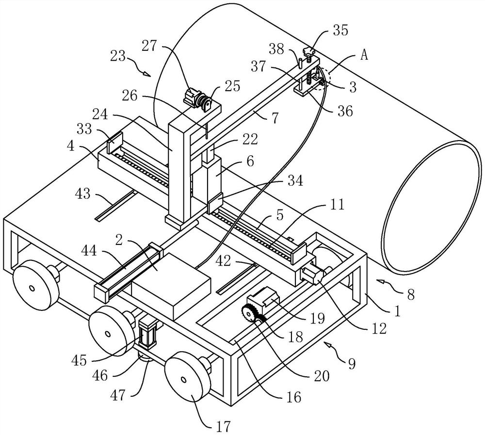
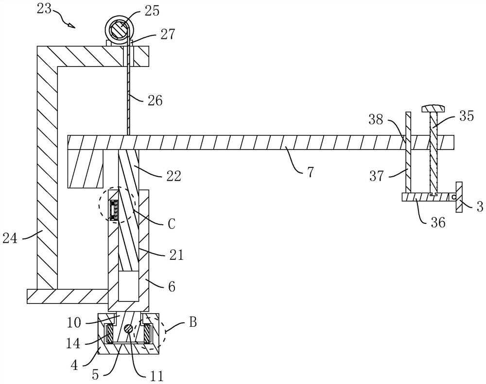
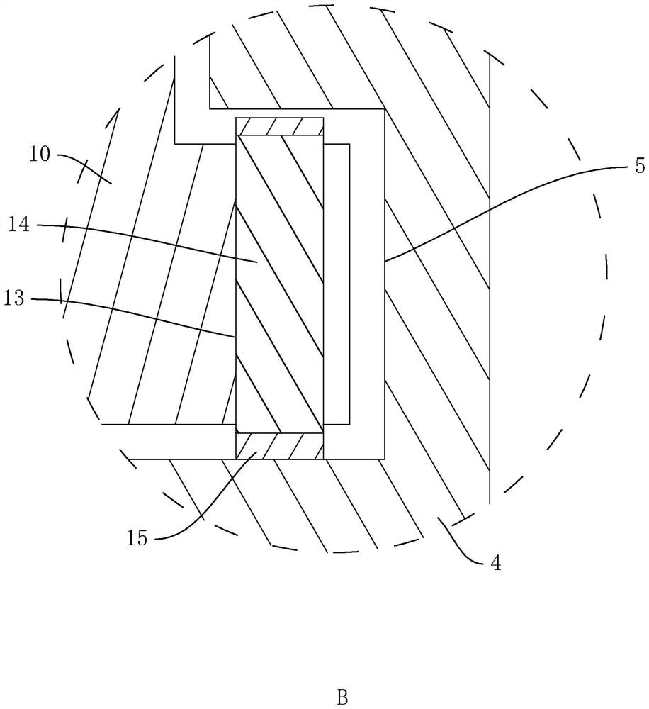
[0035] like figure 1 As shown, the ultrasonic detector for pipeline flaw detection includes a support frame 1 and a detection host 2 arranged on the support frame 1. The detection host 2 is connected with a detection head 3 through a detection line, and the support frame 1 is fixedly connected with a device along its own length. The fixed block 4, the fixed block 4 is provided with a T-shaped first chute 5 along its own length direction, the first chute 5 is slidingly connected with a detection block 6, and the detection block 6 is connected with an extension plate 7, and the detection head 3 is connected on the extension board 7.

[0036] like figure 1 As shown, a detection assembly 8 for driving the detection block 6 to slide along the first chute 5 and a drive assembly 9 for driving the support frame 1 to move are respectively provided on the support frame 1 . Therefore, when the pipeline needs to be detected, the staff can first move the support frame 1 to the side of th...


PUM


Abstract

The invention relates to an ultrasonic detector for pipeline flaw detection, which is applied to the field of pipeline flaw detection, and comprises a support frame and a detection host arranged on the support frame, the detection host is connected with a detection head, the support frame is provided with a fixed block, the fixed block is provided with a first chute, the first chute is internally connected with a detection block in a sliding manner, and the detection block is provided with an extension plate. The detection head is connected to the extension plate and makes contact with the outer edge of the pipeline, the supporting frame is provided with a detection assembly used for driving the detection block to slide along the first sliding groove, and the supporting frame is further provided with a driving assembly used for driving the supporting frame to move. The pipeline flaw detection device has the technical effects that the detection host does not need to be manually carried and the detection head does not need to be manually held in the pipeline detection process, so that the detection process is time-saving and labor-saving, and the pipeline flaw detection efficiency is improved.

Description

technical field [0001] The present application relates to the technical field of non-destructive testing, in particular to an ultrasonic detector for pipeline flaw detection. Background technique [0002] Ultrasonic testing instrument is a testing instrument that uses ultrasonic technology for testing, and is often used for non-destructive testing of pipelines. [0003] In the process of non-destructive testing of the pipeline by the ultrasonic detector in the related art, the operator needs to place the ultrasonic detector on one side of the pipeline, and then stick the detection head of the ultrasonic detector on the outer wall of the pipeline to detect along the pipeline. Afterwards, according to the results of ultrasonic testing, it is possible to detect whether there is damage or defect in the pipeline without damage. [0004] In the process of implementing this application, the inventor found that there are at least the following problems in this technology: during th...

Claims


Application Information

Patent Timeline
Patent Type & Authority Applications(China)
IPC IPC(8): G01N29/04G01N29/22G01N29/265
CPCG01N29/04G01N29/225G01N29/265G01N2291/023G01N2291/0289G01N2291/2634
Inventor 史兴东姬广东吴振飞
Owner 南京力聚工程检测有限公司
Why Eureka
Try Eureka