Flow guide part, dust-gas separation mechanism and cleaning equipment

A technology for separating and cleaning equipment from dust and gas, applied in suction filters and other directions, can solve the problems of reduced dust collection performance, poor dust collection effect, and easily blocked filter structures.

Pending Publication Date: 2022-06-17
KINGCLEAN ELECTRIC
View PDF8 Cites 0 Cited by
  • Summary
  • Abstract
  • Description
  • Claims
  • Application Information

AI Technical Summary

Problems solved by technology

[0003] The invention discloses a deflector, a dust-gas separation mechanism and a cleaning device to solve the problem that during the use of current cleaning devices such as vacuum cleaners, as the working time continues to increase, the filter structure is easily blocked, resulting in a decline in the dust collection performance of the vacuum cleaner , the problem of poor dust collection effect

Method used


Image

  • Flow guide part, dust-gas separation mechanism and cleaning equipment
  • Flow guide part, dust-gas separation mechanism and cleaning equipment
  • Flow guide part, dust-gas separation mechanism and cleaning equipment

Examples


Embodiment Construction

[0026] In order to make the objectives, technical solutions and advantages of the present invention clearer, the technical solutions of the present invention will be clearly and completely described below with reference to the specific embodiments of the present invention and the corresponding drawings. Obviously, the described embodiments are only some, but not all, embodiments of the present invention. Based on the embodiments of the present invention, all other embodiments obtained by those of ordinary skill in the art without creative efforts shall fall within the protection scope of the present invention.

[0027] The technical solutions disclosed by the various embodiments of the present invention will be described in detail below with reference to the accompanying drawings.

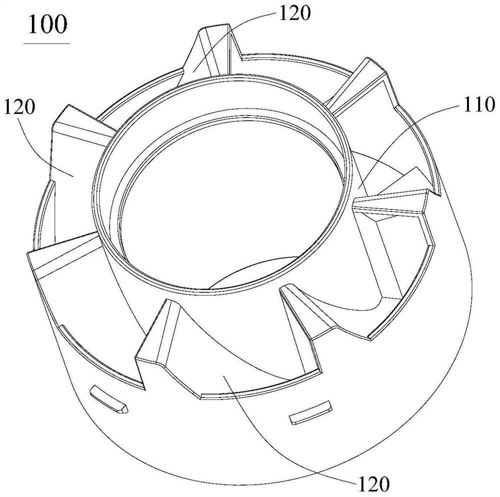
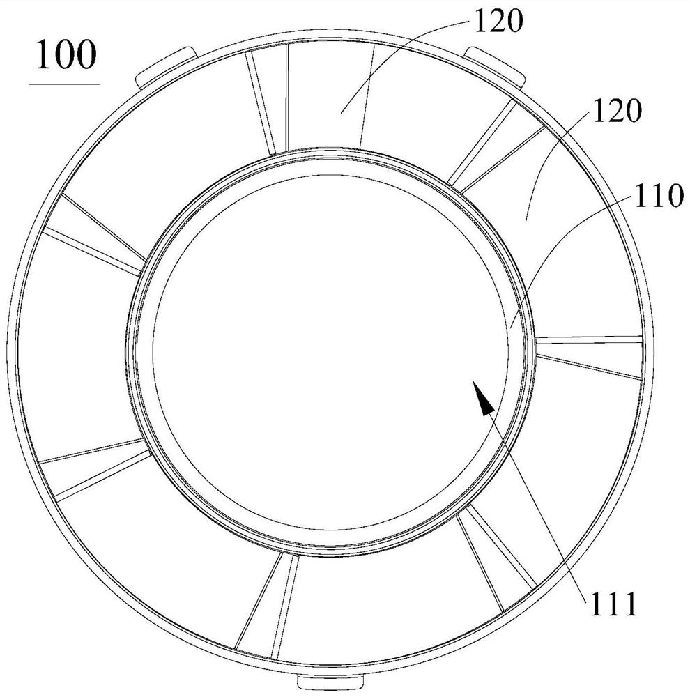
[0028] like Figure 1-Figure 7 As shown, the present application discloses a deflector 100, a dust-gas separation mechanism, and a cleaning device, and the deflector 100 can be applied to the afor...


PUM


Abstract

The invention discloses a flow guide part, a dust-gas separation mechanism and cleaning equipment, the flow guide part is applied to the dust-gas separation mechanism in the cleaning equipment, the flow guide part comprises a plurality of flow guide conical blades, the flow guide conical blades are arranged between a backflow part and a dust collection part in the circumferential direction of the backflow part, and each flow guide conical blade is provided with a flow guide face; the flow guide surfaces spirally extend in the axial direction of the flow guide part, each flow guide surface comprises an axial acceleration section and a tangential acceleration section, the axial acceleration sections are connected to the sides, deviating from the air inlet side, of the tangential acceleration sections, a flow guide space is formed between any two adjacent flow guide surfaces, and the air inlet side communicates with an air inlet of the cleaning equipment through the flow guide space. According to the technical scheme, the problems that the dust collection performance of the dust collector is reduced and the dust collection effect is poor due to the fact that the filtering structure is prone to being blocked along with continuous increase of working time in the using process of existing cleaning equipment such as the dust collector can be solved.

Description

technical field [0001] The invention relates to the technical field of cleaning tools, in particular to a flow guide, a dust-gas separation mechanism and cleaning equipment. Background technique [0002] Cleaning equipment is an extremely important product in people's daily work and life, and with the advancement of technology, more and more electric cleaning equipment has entered people's production and life, such as electric vacuum cleaners, automatic sweepers and automatic Floor mop, etc. Taking a vacuum cleaner as an example, the vacuum cleaner generates suction with the help of a motor, and separates the dust and debris mixed in the gas from the gas with the help of filter structures such as hypa, and continuously generates suction to achieve the purpose of vacuuming. However, during the working process of this vacuum cleaner, as the working time continues to increase, the amount of dust and debris blocked at the filter structure will gradually increase, which will sig...

Claims


Application Information

Patent Timeline
IPC IPC(8): A47L9/16
CPCA47L9/16
Inventor 解永军谢荣誉张和平
Owner KINGCLEAN ELECTRIC
Why Eureka
Try Eureka