
Optical zoom camera module and corresponding portable terminal equipment

An optical zoom and module technology, applied in optics, optical components, cameras, etc., can solve problems affecting user experience, easy sliding of movable carriers, and generation of debris, so as to reduce the risk of stains and facilitate large-scale Mass production and the effect of improving user experience

Active Publication Date: 2022-06-21
NINGBO SUNNY OPOTECH CO LTD
View PDF13 Cites 2 Cited by
  • Summary
  • Abstract
  • Description
  • Claims
  • Application Information

AI Technical Summary

Problems solved by technology

However, on the other hand, the above-mentioned substantial reduction in friction may cause some problems that affect the user experience
For example, because the resistance of the movable carrier in the direction of the guide bar is greatly reduced, sometimes the mobile phone is shaking (for example, some applications use the "shake" function, which may require the user to actively shake the mobile phone), bumping or other certain factors. In a special use state, the movable carrier may slide along the guide bar to cause a collision, which may make an unpleasant sound, and this collision may also inspire the user to get the illusion that there are loose parts inside the mobile phone, so it will Seriously affect user experience
In particular, for long-range telephoto periscope optical zoom modules, which are often equipped with high-end mobile phones, consumers have relatively high requirements for all aspects of mobile phones, and consumers may be more concerned about abnormal sounds and vibrations from mobile phones. Sensitivity, which can have a serious negative impact on the commercial value of guide rod-based optical zoom modules
Finally, because the movable carrier is easy to slide and cause collision, the collision may generate debris, which will cause stains on the screen captured by the module, which will affect the production yield of the module and the reliability of long-term use

Method used


Image

  • Optical zoom camera module and corresponding portable terminal equipment
  • Optical zoom camera module and corresponding portable terminal equipment
  • Optical zoom camera module and corresponding portable terminal equipment

Examples


Embodiment Construction

[0050] For a better understanding of the present application, various aspects of the present application will be described in more detail with reference to the accompanying drawings. It should be understood that these detailed descriptions are merely illustrative of exemplary embodiments of the present application and are not intended to limit the scope of the present application in any way. Throughout the specification, the same reference numerals refer to the same elements. The expression "and / or" includes any and all combinations of one or more of the associated listed items.

[0051] It should be noted that in this specification, the expressions first, second, etc. are only used to distinguish one feature from another feature and do not imply any limitation on the feature. Accordingly, the first body discussed below could also be referred to as a second body without departing from the teachings of the present application.

[0052] In the drawings, the thickness, size and...


PUM


Abstract

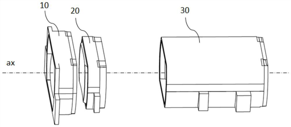
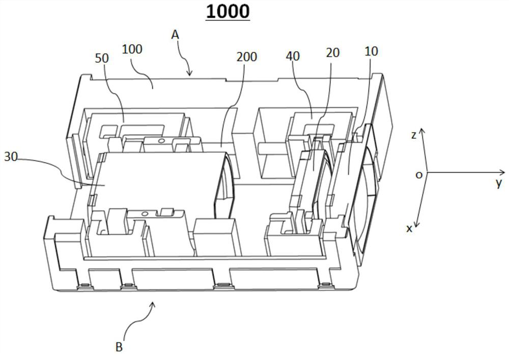
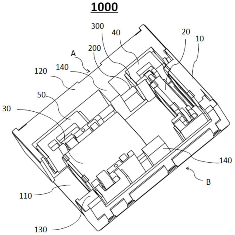
The invention provides an optical zoom module. The optical zoom module comprises a plurality of sub-lenses which are coaxially arranged; the linear guide rods are parallel to the axis; the plurality of carriers are used for mounting the sub-lenses, at least two of the carriers are movable carriers, and each linear guide rod penetrates through at least two movable carriers, so that the at least two movable carriers can move along the linear guide rod respectively; the limiting structure is fixed to the relative position of the linear guide rod and limits the moving stroke of the movable carrier; and the buffer layer is arranged on the end face, facing the movable carrier, of the limiting structure, or arranged on the end face, facing the limiting structure, of the movable carrier, or arranged on the end face of the lens barrel. The invention also provides a corresponding portable terminal device. According to the invention, high-quality continuous optical zooming can be realized, and sound and vibration caused by collision of the movable carrier can be prevented, so that the user experience is improved.

Description

technical field [0001] The present invention relates to the technical field of camera modules, and in particular, the present invention relates to an optical zoom camera module and a corresponding portable terminal device. Background technique [0002] With the improvement of living standards, consumers have higher and higher requirements for the camera functions of mobile phones, tablets and other terminal devices, not only for background blur, night shooting and other effects, but also for telephoto. Consumers need to be able to A terminal device that clearly captures distant images. Optical zoom is a camera module that realizes zoom shooting. Optical zoom is to change the focal length of the lens by changing the distance between the optical lenses of the lens to achieve the purpose of zooming. Zooming here refers to changing the focal length in order to capture the scene at different distances. Furthermore, currently, periscope modules are often used in terminal device...

Claims


Application Information

Patent Timeline
Patent Type & Authority Applications(China)
IPC IPC(8): G03B13/32G02B7/04G03B30/00
CPCG03B13/32G02B7/04
Inventor 袁栋立王启何艳宁廖书伟俞文科邱晨
Owner NINGBO SUNNY OPOTECH CO LTD
Learn More