Beam-expanding collimating optical system and preparation method thereof

A collimating optics and collimating technology, applied in optics, optical components, instruments, etc., can solve problems such as spacing accuracy, parallelism and coaxiality errors, affecting collimation performance, changing spacing, etc., and achieves a large beam expansion magnification , compact structure and high collimation performance

Active Publication Date: 2015-10-14
SUZHOU UNIV
View PDF7 Cites 15 Cited by
  • Summary
  • Abstract
  • Description
  • Claims
  • Application Information

AI Technical Summary

Problems solved by technology

When adjusting the distance between the objective lens and the eyepiece, the system's spacing accuracy, parallelism and coaxiality will bring errors and affect the collimation performance
And with the application of continuous or white ligh

Method used


Image

  • Beam-expanding collimating optical system and preparation method thereof
  • Beam-expanding collimating optical system and preparation method thereof
  • Beam-expanding collimating optical system and preparation method thereof

Examples


Example Embodiment

[0032] Example 1:

[0033] The design requirements of the beam expansion and collimation optical system to be processed in this embodiment: the incident beam is 1.5mm, the divergence angle is 22mrad, and the beam expansion and collimation of 33x is realized. The applicable wavelength range is 488nm~1064m.

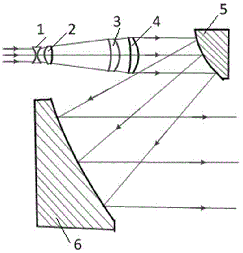
[0034] see attached figure 1, which is a schematic structural diagram of a wide-band high-magnification beam-expanding collimation optical system provided in this embodiment; it includes a transmission beam-expanding collimation group and a reflection beam-expanding collimation group; the transmission beam-expanding collimation group , according to the incident direction of the light, including a beam expansion group consisting of a double concave negative mirror 1 and a double convex positive mirror 2, and a collimation group consisting of the first positive meniscus mirror 3 and the second positive meniscus mirror 4 ; The combined focal length of the beam expansion grou...

Example Embodiment

[0059] Example 2

[0060] see attached Image 6 , a schematic structural diagram of an optical system for wide-band high-magnification beam expansion and collimation provided in this embodiment; this embodiment adopts the same transmission diffusion collimation group as in Embodiment 1, and the reflection beam expansion collimation group adopts a small aperture of concave parabolic mirrors.

[0061] The small-diameter concave parabolic mirror 5 in this embodiment has the same apex curvature as that of the convex parabolic mirror in the embodiment 1, and the sign is opposite, that is, the radius of curvature of the element 5 in Table 1 is changed to -20.1. Since the use of a small concave parabolic mirror will form an intermediate real focus, the overall length of the system will become longer, while when using the small-diameter convex parabolic mirror in Example 1, a virtual focus will be formed, and the length will be shortened. When the small-diameter concave parabolic mi...


PUM

PropertyMeasurementUnit
Lengthaaaaaaaaaa
Widthaaaaaaaaaa

Abstract

The invention discloses a beam-expanding collimating optical system and a preparation method thereof. The optical system comprises a front transmission beam-expanding collimation group and a rear reflection beam-expanding collimation group. According to a light incident direction, the transmission beam-expanding collimation group includes a bi-concave negative lens, a bi-convex positive lens, and two meniscus positive lenses; and the curvatures of the two meniscus positive lenses bend to the light incident direction. The reflection beam-expanding collimation group contains two paraboloid mirrors having identical focus positions; and the two paraboloid mirrors are the small-caliber paraboloid mirror and the large-caliber paraboloid mirror and the surface of the large-caliber paraboloid mirror is an off-axis concave surface. According to the collimating optical system, collimation and beam expanding can be provided for a laser with any laser wavelength in a broadband range or white laser and no moving compensation component is needed. The system has advantages of compact structure, small size, high beam-expanding multiplying power, and excellent collimation performance. The system can be applied to fields of holographic imaging, optical test, and laser radar and the like.

Description

technical field [0001] The invention relates to a compact wide-band high-magnification beam-expanding collimating optical system and a preparation method thereof. Background technique [0002] In many applications such as optical detection, spectral calibration, lidar, security, etc., it is necessary to shape the beam to achieve a very small angle emission of the beam, so as to achieve long-distance transmission or optimal coupling of the beam. At present, the optical system beam expansion collimation can be divided into two types. One is developed for the application of laser beams in a single wavelength band, and the corresponding beam expansion collimation systems include transmission type, reflection type and the combination of the two; the other The first is for laser applications at multiple wavelengths. This structure changes the distance between the eyepiece and the objective lens to adapt to different wavelengths while keeping the parameters of the optical element u...

Claims


Application Information

Patent Timeline
IPC IPC(8): G02B27/09G02B27/30
CPCG02B27/0955G02B27/0983G02B27/30
Inventor 周建康陈新华陈宇恒
Owner SUZHOU UNIV
Why Eureka
Try Eureka