CT (computed tomography) machine and X-ray collimator thereof

An X-ray and collimator technology, applied in the field of medical machinery, can solve problems such as difficulty in ensuring the consistency of anti-scattering, many parts of the X-ray collimator, and inconsistent anti-scattering effect, so as to improve anti-scattering effect, accurate Good direct effect and simple structure

Active Publication Date: 2014-06-25
NEUSOFT MEDICAL SYST CO LTD
View PDF8 Cites 17 Cited by
  • Summary
  • Abstract
  • Description
  • Claims
  • Application Information

AI Technical Summary

Problems solved by technology

[0012] The current X-ray collimator, in the first configuration, uses sheet metal stamping to form a bent lattice-like member, which is formed by bonding figure 1 For the X-ray collimator shown, see the Chinese patent No. 03826552.4 and titled "An Anti-scattering X-ray Collimator for CT Scanning Device" for details; , resulting in low precision
In the second setting method, the array grid holes are stacked and accumulated to form figure 1 For the X-ray collimator shown, see the Chinese patent No. 200810009502.5 and titled "Stacked CT Collimator and Its Preparation Method" for details; It is necessary to ensure that each layer has a uniform size of the primary ray penetration area, and it is difficult to ensure the consistency of anti-scattering
In the third setting method, an X-ray collimator similar to 3D printing can be used. For details, see the Chinese patent No. 02144468.4 and the name "Method for Manufacturing Scattering Grating or Collimator"; in the third setting In the printing method, the wall thickness of the through hole formed by printing is relatively thick, which will greatly block the primary ray, and the anti-scattering effect will be inconsistent due to the uneven wall thickness.
In the fourth setting mode, tenon-tenon connection type X-ray collimator can be used, see the US patent No. 20070258566A1 and the name "ANTI-SCATTER-GRID" for details; in the fourth setting mode, the composition X There are many components in the ray collimator, and the manufacturing and assembly process is very complicated

Method used


Image

  • CT (computed tomography) machine and X-ray collimator thereof
  • CT (computed tomography) machine and X-ray collimator thereof
  • CT (computed tomography) machine and X-ray collimator thereof

Examples


Embodiment Construction

[0067] The core of the invention is to provide an X-ray collimator for a CT machine, which has a simple structure and better collimation effect.

[0068] Another core of the present invention is to provide a CT machine with the above-mentioned X-ray collimator, which has high detection accuracy.

[0069] In order to enable those skilled in the art to better understand the solution of the present invention, the present invention will be further described in detail below in conjunction with the accompanying drawings and specific embodiments.

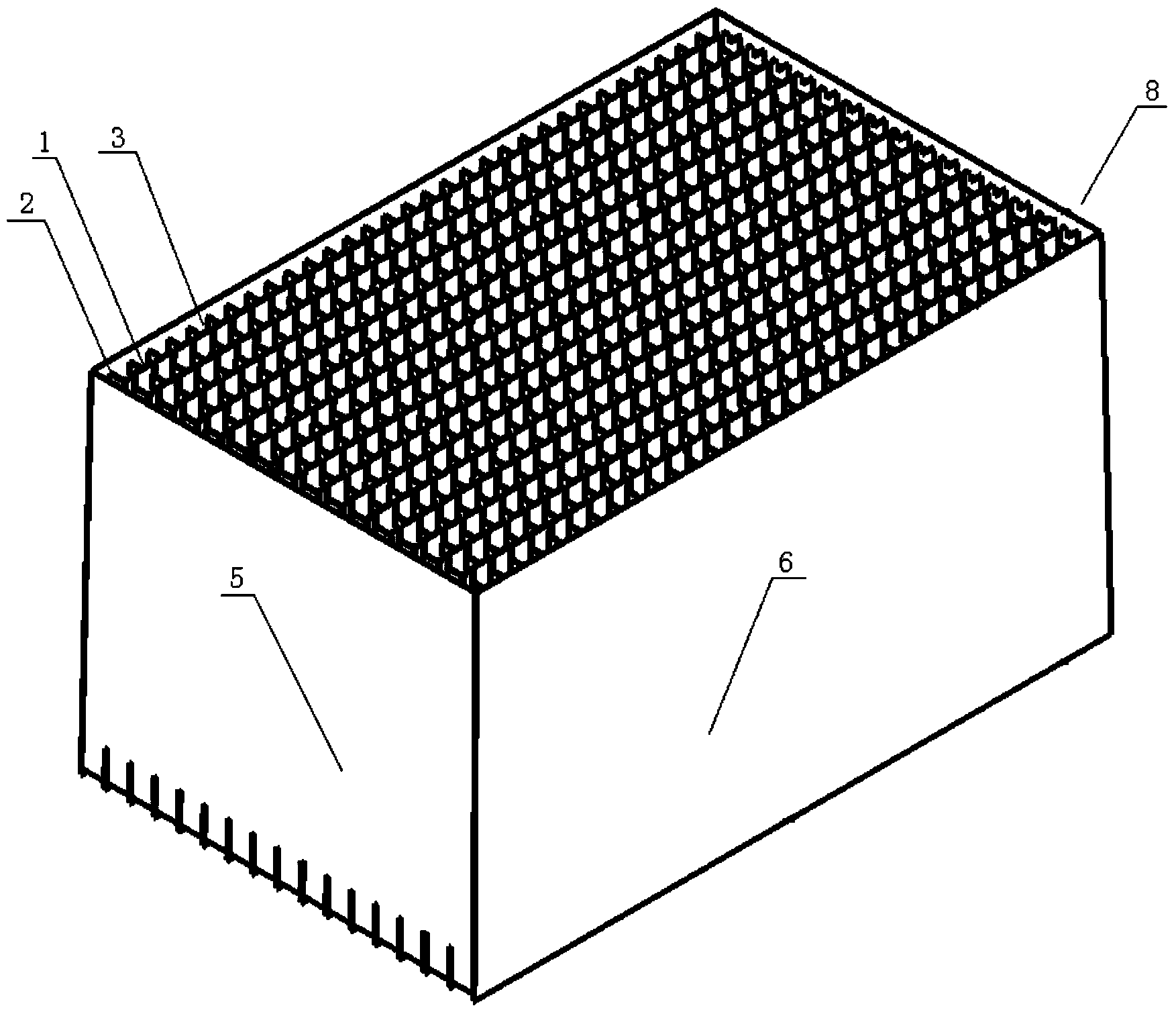
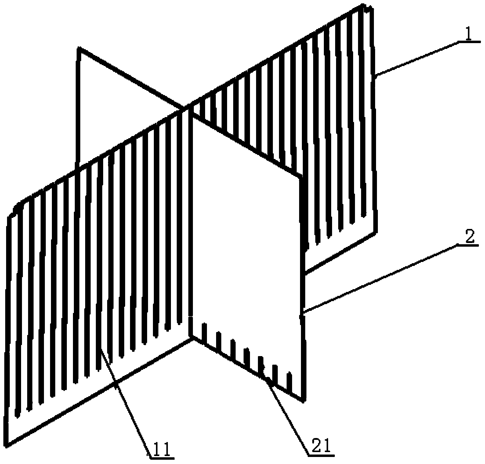
[0070] Please refer to figure 2 and Figure 16 , figure 2 A schematic diagram of the three-dimensional structure of the X-ray collimator provided by the present invention in a specific embodiment; Figure 16 for figure 1 The schematic diagram of the three-dimensional structure of the X-ray collimator installed on the X-ray detector is shown.

[0071] The X-ray collimator 8 of the present invention includes several first plates 1 and...


PUM


Abstract

The invention provides a CT (computed tomography) machine and an X-ray collimator thereof. A good collimation effect can be realized. The X-ray collimator comprises a plurality of first plates and second plates. The first plates and the second plates respectively peripherally and axially extend on the CT machine and are spliced with one another, a through hole is formed by each two adjacent first plates and the two corresponding adjacent second plates in an enclosed manner, and extension lines of various side walls of each through hole intersect with one another at a focal point of an X-ray source, so that X-rays can conveniently linearly penetrate the through holes. The CT machine and the X-ray collimator have the advantages that the extension lines of the various side walls of each through hole intersect with one another at the focal point of the X-ray source, the through holes are perforated in extension directions of the various X-rays corresponding to the through holes, accordingly, the X-rays emitted from the focal point of the X-ray source can linearly penetrate the through holes and finally reach a detection unit of an X-ray detector without being blocked, and the good collimation effect can be realized; scattered light rays can be absorbed and blocked by the side walls of the through holes, so that interference of the scattered light rays on the X-rays positioned in the through holes can be prevented, an anti-scattering effect can be improved, and the detection precision can be enhanced.

Description

technical field [0001] The invention relates to the technical field of medical machinery, in particular to an X-ray collimator of a CT machine. The present invention also relates to a CT machine with the above-mentioned X-ray collimator. Background technique [0002] In a CT machine, an object to be inspected is transmitted by the X-rays emitted by an X-ray source with an approximate point-like focus, and the two-dimensional attenuation distribution of the X-rays passing through the object to be inspected is measured by the detector, and the distribution data is processed by a computer Generate corresponding tomographic images. [0003] In current medical CT machines, solid detectors are mainly used for X-ray measurement. This solid-state detector is usually an X-ray photoelectric receiver array formed by a number of optoelectronic semiconductor units arranged in a grid matrix, usually a pixel matrix of 16×16 or 16×32 pixels. [0004] Ideally, X-rays propagate in a straig...

Claims


Application Information

Patent Timeline
Patent Type & Authority Applications(China)
IPC IPC(8): A61B6/03
CPCG01N23/046G01N2223/316G21K1/025
Inventor 于军
Owner NEUSOFT MEDICAL SYST CO LTD
Why Eureka
Try Eureka