
Novel armature assembly for relay

A relay and armature technology, applied in the field of armature components for new relays, can solve the problems of inability to contact with static contacts, inability to drive moving reeds to rotate, and relays not working normally, so as to avoid inability to contact, change reset capability, reduce The effect of a small overall volume

Active Publication Date: 2022-06-21
徐州乔南仪表有限公司
View PDF7 Cites 0 Cited by
  • Summary
  • Abstract
  • Description
  • Claims
  • Application Information

AI Technical Summary

Problems solved by technology

[0004] At present, the existing armature assembly for relays, when it is energized, the armature drives the moving reed to rotate and squeeze the return spring, but with the shape of the return spring As the variable gradually increases, the elastic force of the return spring will also increase accordingly. When the elastic force of the return spring is greater than the magnetic force between the armature and the iron core, the armature will not be able to drive the moving reed to rotate, thus making it easy to make the moving reed mounted on the moving reed. The moving contact cannot make contact with the static contact, causing the relay to fail to work properly

Method used


Image

  • Novel armature assembly for relay
  • Novel armature assembly for relay
  • Novel armature assembly for relay

Examples


Embodiment Construction

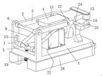
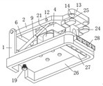
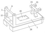
[0029] Secondly, the lower ends of the inner walls on both sides of the through groove 5 are vertically provided with chute 15, and the two ends of the movable shaft 7 are respectively located in the inner cavities of the two chute 15 and are adapted to the chute 15, and the movable shaft 7 can move along the The longitudinal direction of the chute 15 slides up and down. When the movable shaft 7 slides up and down in the vertical direction, it can adjust the inclination angle of the elastic telescopic rod 9, thereby adjusting the return spring embedded in the elastic telescopic rod 9 to move the reed 2 The amount of thrust generated.

[0030]Further, a connecting sleeve 16 is fixedly connected to the middle of the movable shaft 7, and the inner cavity of the connecting sleeve 16 is movably connected with a connecting column 171, and the lower end of the connecting column 171 is fixedly connected with an adjusting rod 17, and the outside of the adjusting rod 17 is provided with ...


PUM


Abstract

The invention discloses a novel armature assembly for a relay, and relates to the technical field of relays, the novel armature assembly comprises a support, a movable contact spring, an armature block and an elastic telescopic rod, the support is arranged to be in a horizontally-placed L shape, a through groove is formed in the middle of one side face of the support in a penetrating mode, and a fixing shaft fixedly connected with the support is arranged at the upper end of an inner cavity of the through groove; a movable shaft is arranged at the lower end of an inner cavity of the through groove, the movable contact spring is located at the upper end of the support and horizontally placed, one end of the movable contact spring is movably connected to the outer side of the fixed shaft in a sleeving mode and can rotate around the fixed shaft, and the two side faces of the movable contact spring are attached to the upper ends of the inner walls of the two sides of the through groove respectively. The armature block is installed in the middle of the inner wall of one end of the installation groove, the hollow cylinder and the movable contact spring are installed on the same side of the support, and compared with a traditional relay that a reset spring and a movable contact spring are installed on the two sides of the support respectively, the overall size of the device is effectively reduced under the condition that rotation of the movable contact spring is not affected.

Description

technical field [0001] The invention relates to the technical field of relays, in particular to a novel armature assembly for relays. Background technique [0002] The relay is an electrical control device, which is an electrical appliance that causes the controlled quantity to undergo a predetermined step change in the electrical output circuit when the change of the input quantity meets the specified requirements. It has an interactive relationship between the control system and the controlled system. Usually used in automatic control circuits, it is actually an "automatic switch" that uses a small current to control the operation of a large current. Therefore, it plays the role of automatic adjustment, safety protection, and conversion circuit in the circuit. [0003] The armature generally refers to the iron block that is sucked up and down by the electromagnet in the electromagnetic relay, and the working circuit is closed after the movement. It is not necessarily a m...

Claims


Application Information

Patent Timeline
Patent Type & Authority Applications(China)
IPC IPC(8): H01H50/18H01H50/54H01H50/56H01H1/50
CPCH01H50/18H01H50/54H01H50/56H01H1/50
Inventor 闫成州韩金玲李怀刚
Owner 徐州乔南仪表有限公司
Learn More