Measuring drill rod bending machine for road surveying and mapping

A technology of bending processing and bending mechanism, which is applied in the field of measuring brazing bending processing machines for highway surveying and mapping, and can solve problems such as poor practicability, deflection of bending angle, and dislocation of small rings

Active Publication Date: 2022-06-24
南通天正信息技术服务有限公司
View PDF6 Cites 0 Cited by
  • Summary
  • Abstract
  • Description
  • Claims
  • Application Information

AI Technical Summary

Problems solved by technology

[0003] At present, the following problems exist in the process of bending the upper part of the measuring rod into a small ring: a. The existing measuring rod bending machine needs to manually adjust the position of the measuring rod when placing the measuring rod, so as to ensure that the upper part of the measuring rod can just be bent into a small ring For small rings, most of the existing braze bending machines can only bend one or several specific brazes of different specifications, and cannot flexibly realize the bending of a variety of different specifications of brazes, which is not practical. Strong; b. The existing measuring brazing bending machine has a bending angle deflection when bending the measuring brazing, which makes the two ends of the small ring misaligned.

Method used


Image

  • Measuring drill rod bending machine for road surveying and mapping
  • Measuring drill rod bending machine for road surveying and mapping
  • Measuring drill rod bending machine for road surveying and mapping

Examples


Embodiment Construction

[0031] Embodiments of the present invention will be described below with reference to the accompanying drawings. During this process, in order to ensure the clarity and convenience of the description, we may exaggerate the width of the lines or the size of the components in the illustrations.

[0032] In addition, the following terms are defined based on the functions in the present invention, and may be different according to the user's intention or convention. Therefore, these terms are defined based on the entire content of this specification.

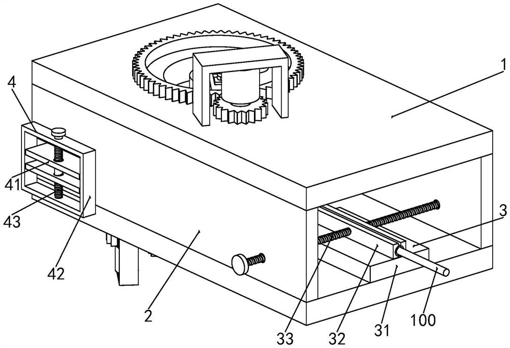
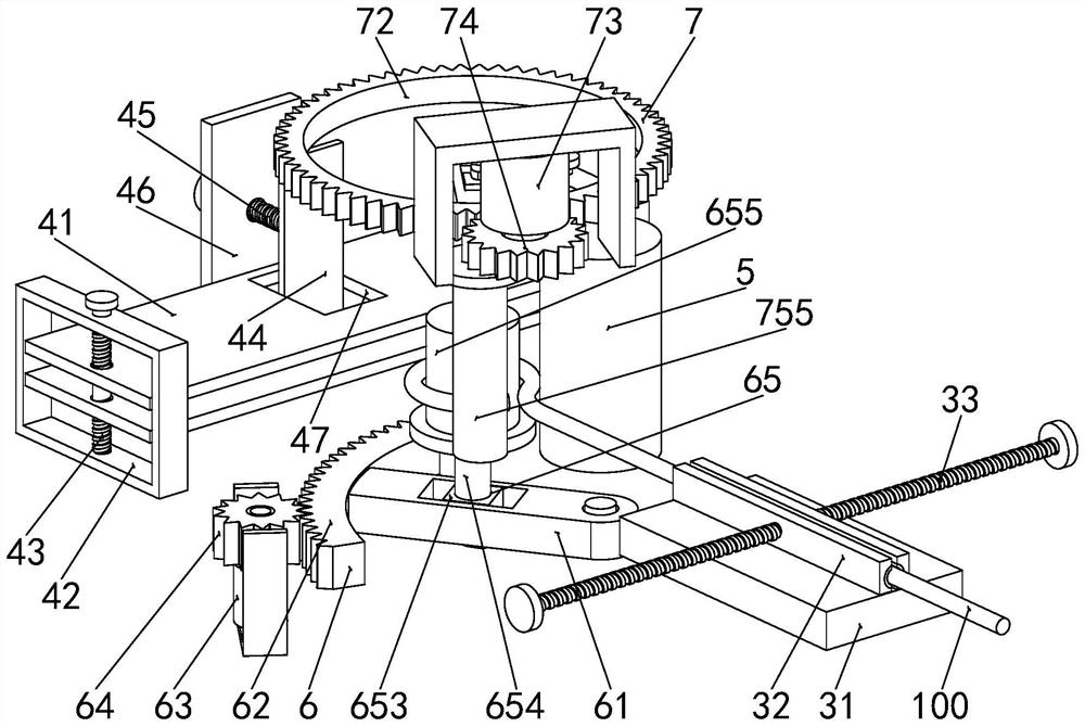
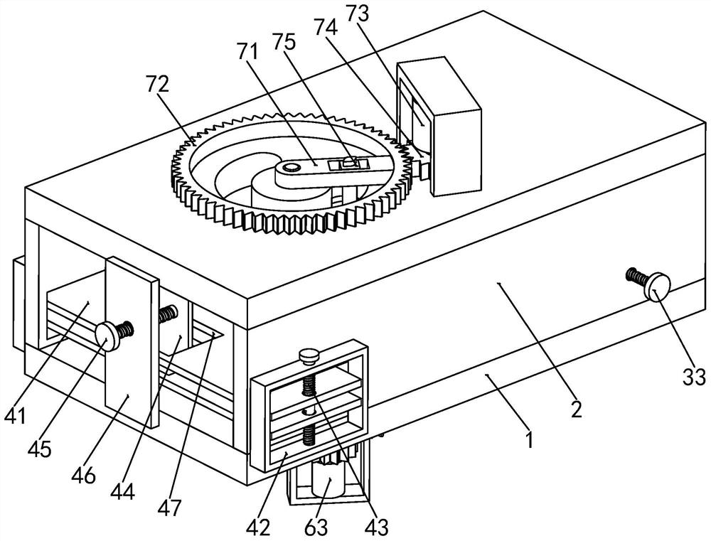
[0033] see Figure 1 to Figure 4 , a measuring and bending machine for highway surveying and mapping, comprising a processing plate 1, a side plate 2, a clamping mechanism 3, a positioning mechanism 4 and a bending device. A side plate 2 is connected between the front and rear sides of each of the processing plates 1 , a positioning mechanism 4 is arranged between the left sides of the two processing plates 1 , and a clamping mech...


PUM


Abstract

The invention relates to the technical field of measuring drill rod machining, in particular to a measuring drill rod bending machine for road surveying and mapping, which comprises two machining plates, side plates, a clamping mechanism, a positioning mechanism and a bending device, the two machining plates are symmetrically distributed up and down, and the side plates are connected between the front sides and the rear sides of the two machining plates; a positioning mechanism is arranged between the left sides of the two machining plates, a clamping mechanism is arranged on the right side of the upper end face of the lower machining plate, and a bending device is arranged between the two machining plates. According to the device, bending machining can be carried out on the measuring drill rods of various different specifications by adjusting the positions of the first bending shaft and the second bending shaft, the first bending shaft is used for carrying out first-time bending machining on the measuring drill rods, and then the second bending shaft is used for carrying out second-time bending forming machining on the measuring drill rods.

Description

technical field [0001] The invention relates to the technical field of measuring brazing processing, in particular to a measuring brazing bending processing machine for highway surveying and mapping. Background technique [0002] The measuring drill is a tool, which has functions such as calibrating the position of the ruler point and calculating the number of ruler segments to be measured. The diameter is different according to specific requirements, generally 8mm, the upper part of the measuring drill is bent into a small ring, and the lower part is sharpened. [0003] At present, there are the following problems in the process of bending the upper part of the test drill into a small ring: a. The existing test drill bending machine needs to manually adjust the position of the test drill when placing the test drill, so as to ensure that the upper part of the test drill can just be bent into a Small ring, most of the existing measuring and bending machines can only bend on...

Claims


Application Information

Patent Timeline
Patent Type & Authority Applications(China)
IPC IPC(8): B21F1/00
CPCB21F1/00
Inventor 刘飞张红燕
Owner 南通天正信息技术服务有限公司
Why Eureka
Try Eureka