Road measuring device based on information technology

A technology of road measurement and information technology, applied in the field of road measurement devices, can solve problems such as distance deviation, direction deviation, time-consuming and labor-intensive problems

Active Publication Date: 2021-09-10
WENZHOU UNIVERSITY
View PDF5 Cites 0 Cited by
  • Summary
  • Abstract
  • Description
  • Claims
  • Application Information

AI Technical Summary

Problems solved by technology

[0003] In road construction, use the GPS measuring instrument to set out the design points, find out the design point coordinates (X, Y coordinates), and finally mark the points determined by the GPS measuring instrument for subsequent construction. In the actual setting out, the GPS measuring instrument is placed vertically on the ground, and there is a deviation in the direction and distance between the first measured position and the coordinates of the design point, which requires the technician to move and make multiple adjustments in conjunction with real-time measurement. It is time-consuming and labor-intensive to determine the correct point. For this reason, we propose a road measurement device based on information technology

Method used


Image

  • Road measuring device based on information technology
  • Road measuring device based on information technology
  • Road measuring device based on information technology

Examples


Embodiment 1

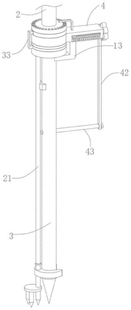
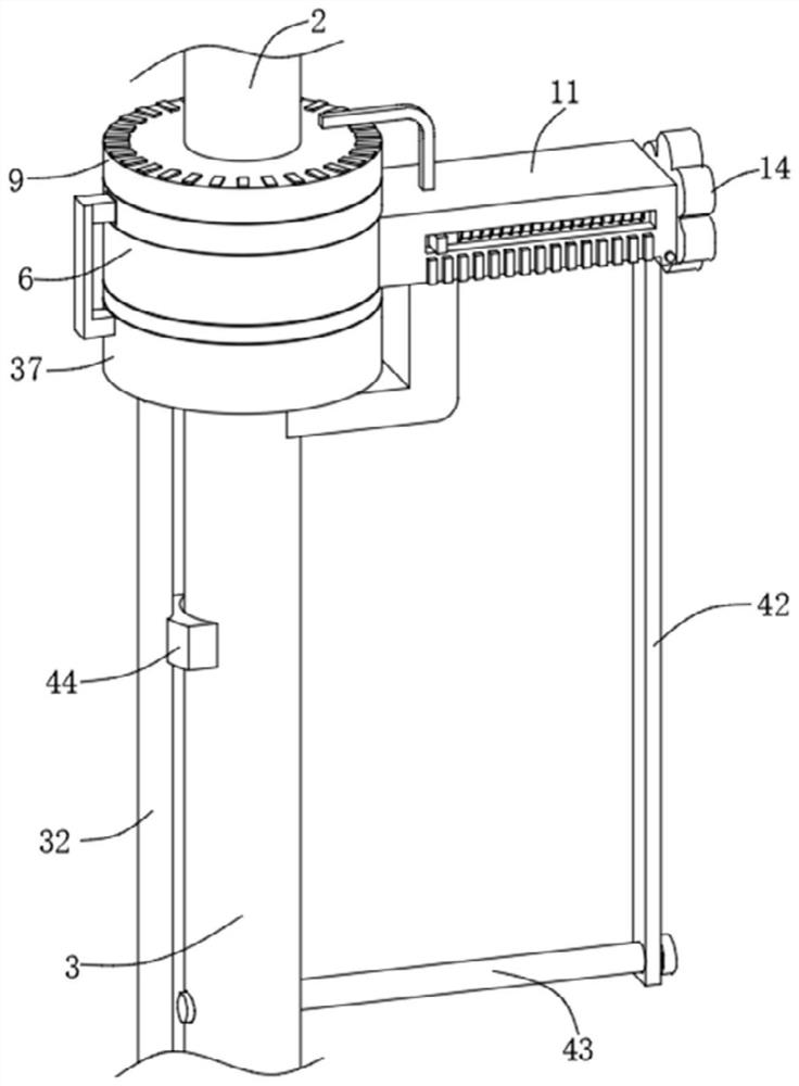
[0030] see Figure 1-2 , Figure 4-8 and Figure 11 , the present invention provides a technical solution: a road measurement device based on information technology, including a receiver 1, the bottom of which is fixedly connected with a telescopic rod 2; also includes an insertion rod 3 located below the telescopic rod 2; Assembly 4, the rotation assembly 4 used to adjust the angle deviation of the insertion rod 3 is located between the telescopic rod 2 and the insertion rod 3; the displacement assembly 13, the displacement assembly 13 used to adjust the distance deviation of the insertion rod 3 is provided on the side of the rotation assembly 4.

[0031] Wherein, the rotating assembly 4 includes a gear 5 connected and fixed to the bottom end of the telescopic rod 2, the outer surface of the gear 5 is meshed with an inner toothed ring 6, and the top surface of the inner toothed ring 6 is fixedly connected with a first rotating ring 7. The outer surface of the first rotating...

Embodiment 2

[0038] Reference attached Figure 9-10 Embodiment 2 is described. This embodiment is further described relative to Embodiment 1. The support assembly 21 includes a second fixed plate 22 located above the insertion rod 3 and connected to the bottom end of the telescopic rod 2. The second fixed plate 22 has a The first rotating groove 23, the outer surface of the second fixed disk 22 is provided with the second rotating groove 24 communicating with the first rotating groove 23, and the inner side of the first rotating groove 23 is provided with the second rotating groove 22 that is rotatably matched with the second fixed disk 22. The third rotating ring 25, the first pressing block 26 with an inclined bottom surface is movably fitted in the first rotating groove 23, and the bottom end of the first pressing block 26 is press-fitted with the third rotating groove. The connecting block 27, the first spring 28 is hooked between the first pressing block 26 and the third rotating ring...

Embodiment 3

[0041] Reference attached image 3 The third embodiment is described. This embodiment is further described relative to the first embodiment. The displacement assembly 13 includes an adjustment handle 14. The bottom surface of the fixed plate 11 is provided with a second movable groove 15. The side of the fixed plate 11 is provided with a second movable groove. The third movable groove 16 connected to the movable groove 15, the adjustment handle 14 is fixedly connected with the threaded rod 17 penetrating into the second movable groove 15, and the second movable groove 15 is slidably fitted with a movable rod 3 connected and fixed. plate 18, the movable plate 18 has an L-shaped structure, the threaded rod 17 is threadedly connected with the movable plate 18, the end of the threaded rod 17 is rotatably matched with the fixed plate 11, and the side of the fixed plate 11 is fixedly connected with a position scale 19. A second pointer 20 connected and fixed to the movable plate 18 ...


PUM


Abstract

The invention discloses a road measuring device based on an information technology. The device comprises a receiver, wherein the bottom of the receiver is fixedly connected with a telescopic rod; an inserting rod positioned under the telescopic rod; a rotating assembly used for adjusting the angle deviation of the inserting rod and arranged between the telescopic rod and the inserting rod; and a displacement assembly used for adjusting the distance deviation of the inserting rod and arranged on the side face of the rotating assembly. The direction deviation of the inserting rod is adjusted by rotating the fixing plate through the right hand, the adjusting plate is pressed through the left hand, the supporting rod moves downwards, the inserting rod is jacked up, the telescopic rod is pressed through a second abutting block, and the angle of the fixing plate after adjustment is kept unchanged; and then, the adjusting handle is rotated, the inserting rod moves in the direction of the second movable groove, and therefore, the displacement deviation of the inserting rod is adjusted. The structure is simple and convenient, the adjusting efficiency is high, time and labor are saved, and the adjusting precision is high.

Description

technical field [0001] The invention relates to the technical field of road surveying devices, in particular to a road surveying device based on information technology. Background technique [0002] The GPS measuring instrument uses the GPS global satellite positioning system to provide real-time navigation and positioning information such as longitude, latitude, and elevation. Using the positioning function of GPS, the coordinates of each point are obtained, and then the distance, area and other data are calculated by mathematical methods. [0003] In road construction, use the GPS measuring instrument to set out the design points, find out the design point coordinates (X, Y coordinates), and finally mark the points determined by the GPS measuring instrument for subsequent construction. In the actual setting out, the GPS measuring instrument is placed vertically on the ground, and there is a deviation in the direction and distance between the first measured position and the...

Claims


Application Information

Patent Timeline
Patent Type & Authority Applications(China)
IPC IPC(8): G01C15/00G01D11/30
CPCG01C15/00G01D11/30
Inventor 黄兴利李小志周飞
Owner WENZHOU UNIVERSITY
Why Eureka
Try Eureka