
Structure for connecting but not connecting top of retaining wall with main body structure

A technology of main structure and retaining wall, applied in underwater structures, basic structure engineering, buildings, etc., can solve problems such as large structural torsion effect, difficult to solve, and the displacement ratio between layers of the structure exceeds the specification requirements, so as to achieve guaranteed displacement indicators, reduce large-scale changes, and avoid effects with large reverse effects

Pending Publication Date: 2022-06-24
TONGJI UNIV ARCHITECTURAL DESIGN INST GRP CO LTD
View PDF0 Cites 0 Cited by
  • Summary
  • Abstract
  • Description
  • Claims
  • Application Information

AI Technical Summary

Problems solved by technology

In the conventional design in the past, the purpose of connecting the retaining wall and the main structure as a whole was achieved by directly connecting the structural columns, structural beams and the main structure floor with the retaining wall. Due to the uneven layout of the retaining wall affects the overall stiffness of the structure, resulting in uneven distribution of structural stiffness, the large torsional effect of the structure under earthquakes, and the displacement ratio between floors of the structure far exceeds the code requirements and is difficult to solve

Method used


Image

  • Structure for connecting but not connecting top of retaining wall with main body structure
  • Structure for connecting but not connecting top of retaining wall with main body structure
  • Structure for connecting but not connecting top of retaining wall with main body structure

Examples


Embodiment 1

[0038] This embodiment provides a structure in which the top of the retaining wall is connected to but not connected to the main structure.

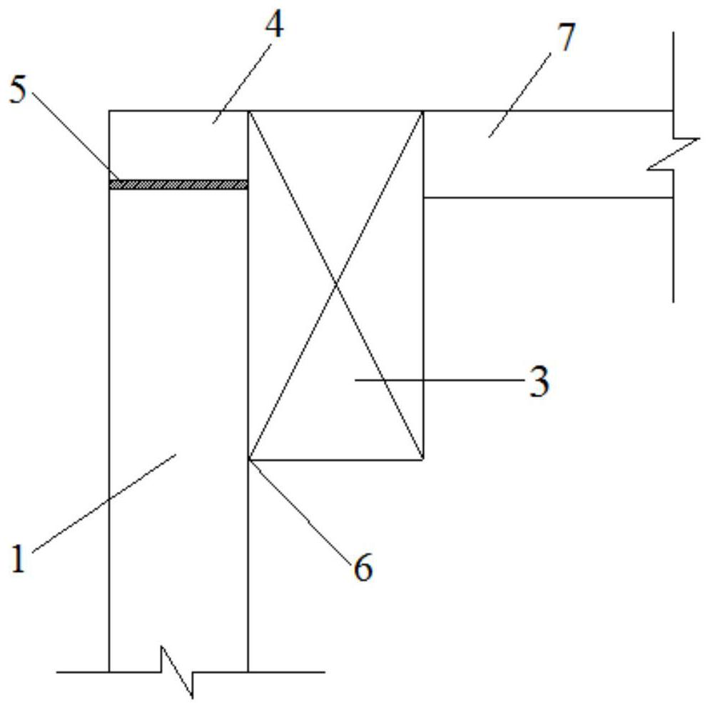
[0039] Existing designs such as figure 1 As shown, the design of this embodiment is as follows Figure 2-3 As shown, a structure in which the top of the retaining wall is connected to but not connected to the main structure includes a retaining wall 1, a pick ear 4 and a main structure, wherein the main structure includes a structural column 1, a structural beam 3 and a main structural floor 7; The height of retaining wall 1 is 6 meters and the thickness is 300mm; the thickness of pick ears 4 is 150mm;

[0040] There are two structural columns 2 along the length of the retaining wall 1, and they are completely separated from the retaining wall 1. The cross-frame structural beam 3 above the structural column 2, the side of the structural beam 3 and the top side of the retaining wall 1 pass through the lateral soil. The thrust is compres...


PUM


Abstract

The invention relates to the technical field of constructional engineering, in particular to a structure with the top of a retaining wall connected but not connected with a main structure, which comprises the retaining wall, a lifting lug and the main structure, and the main structure comprises a structural column, a structural beam and a main structure floor; a plurality of structural columns are arranged in the length direction of the retaining wall and are completely separated from the retaining wall, structural beams are transversely erected above the structural columns, the side faces of the structural beams and the side face of the top of the retaining wall are naturally pressed through soil side thrust, the side faces of the structural beams are connected with lifting lugs, and the side, away from the lifting lugs, of each structural beam is connected with a main body structural floor. Wherein the lifting lug is arranged above the retaining wall, and a slit is formed between the lifting lug and the retaining wall. The retaining wall is lower than 7 meters, the top of the retaining wall is connected but not connected with the main body structure, it is ensured that the structural rigidity of the retaining wall does not affect the overall rigidity of the main body structure, only lateral soil thrust is transmitted, the problem that the structural torsion effect is large under an earthquake is effectively avoided, and the displacement ratio between structural layers meets the standard requirement.

Description

technical field [0001] The invention relates to the technical field of construction engineering, in particular to a structure in which the top of a retaining wall is connected but not connected to a main structure. Background technique [0002] In recent years, with the rapid development of my country's architectural design industry, the construction site has become more and more complicated. In the design of mountain and sloping buildings, non-four-sided retaining walls are often set up due to the terrain height difference, that is, there are retaining walls on only a few sides of the structure instead of retaining walls on all four sides. In the previous conventional design, the purpose of connecting the retaining wall and the main structure as a whole is achieved by directly connecting the structural columns, structural beams and the main structure floor with the retaining wall. Because the uneven arrangement of retaining walls affects the overall stiffness of the struct...

Claims


Application Information

Patent Timeline
Patent Type & Authority Applications(China)
IPC IPC(8): E02D29/02E02D29/16
CPCE02D29/02E02D29/16
Inventor 丁祝红孔庆宇张涛闵籽涵李丰晨唐方园
Owner TONGJI UNIV ARCHITECTURAL DESIGN INST GRP CO LTD
Learn More