High-voltage direct-current interference corrosion rate measuring device and method

A corrosion rate, high-voltage direct current technology, which is applied to measuring devices, weather resistance/light resistance/corrosion resistance, instruments, etc., can solve problems such as high cost, high hardware cost, and time interval uncertainty

Pending Publication Date: 2022-06-24
ELECTRIC POWER RESEARCH INSTITUTE, CHINA SOUTHERN POWER GRID CO LTD +1
View PDF0 Cites 0 Cited by
  • Summary
  • Abstract
  • Description
  • Claims
  • Application Information

AI Technical Summary

Problems solved by technology

[0003] When the high-voltage DC grounding pole is operated in a single pole, the corrosion situation of buried metal structures near the high-voltage DC grounding pole under the two states of anode operation and cathode operation under the interference of high-voltage direct current is obtained. The implementation methods and existing problems of the existing technology generally include the following situations : First, setting detection points at the sending end grounding electrode and receiving end grounding electrode at the same time, and setting up a set of detection equipment at both ends respectively, the hardware cost is relatively large; second, the detection time range of the detection point of the buried metal structure Covering the two processes of anode operation and cathode operation of HVDC unipolar operation, however, the time interval between anode operation and cathode operation of HVDC unipolar operation has a large uncertainty, which may be several Hours, days, months, or even years, so if you want to ensure that the detection data covers two interference processes, the cost is high and the timeliness is poor

Method used


Image

  • High-voltage direct-current interference corrosion rate measuring device and method
  • High-voltage direct-current interference corrosion rate measuring device and method

Examples


Embodiment Construction

[0038] The technical solutions in the embodiments of the present application will be clearly and completely described below with reference to the drawings in the embodiments of the present application. Obviously, the described embodiments are only a part of the embodiments of the present application, but not all of the embodiments. Based on the embodiments in the present application, all other embodiments obtained by those of ordinary skill in the art without creative efforts shall fall within the protection scope of the present application.

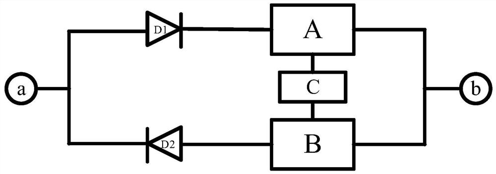
[0039] Next, a detailed introduction of the HVDC interference corrosion rate measurement device of the present application is given, please refer to figure 1 , figure 1 A schematic structural diagram of a high-voltage direct current interference corrosion rate measurement device provided in the embodiment of the present application, the device may include:

[0040] The first corrosion rate probe a, the second corrosion rate probe b, the...


PUM


Abstract

The invention discloses a high-voltage direct-current interference corrosion rate measuring device and method. The device comprises a first corrosion rate probe, a second corrosion rate probe, a first anti-interference unit, a second anti-interference unit, a first data acquisition unit, a second data acquisition unit and a data processing unit. The two corrosion rate probes can be buried in any target detection position in the soil environment of the high-voltage direct-current grounding electrode, the two data acquisition units acquire the current value of current to be detected flowing through the two corrosion rate probes, the data processing unit acquires the current value, and the corrosion rate of the high-voltage direct-current grounding electrode can be detected according to the exposure area of the corrosion rate probes. The corrosion rate of the buried metal in the soil environment can be respectively determined when the anode and the cathode of the high-voltage direct-current grounding electrode operate. Furthermore, even if no buried metal exists near the high-voltage direct-current grounding electrode, the device can predict the corrosion rate of the buried metal to be built near the high-voltage direct-current grounding electrode based on the detection of the target detection position, and can predict and analyze the corrosion condition of the planned buried metal.

Description

technical field [0001] The present application relates to the technical field of electrical corrosion measurement, and more particularly, to a high-voltage direct current interference corrosion rate measurement device and method. Background technique [0002] In recent years, with the rapid development of HVDC transmission technology, the problem of electrochemical corrosion caused by HVDC grounding interference has become more and more prominent. [0003] When the HVDC grounding electrode is operated in a unipolar state, the corrosion situation of the buried metal structures near the HVDC grounding electrode under the two states of anode operation and cathode operation is obtained due to the HVDC interference. The implementation methods and existing problems in the prior art generally include the following situations : First, set detection points at the sending end grounding electrode and receiving end grounding electrode at the same time, and set up a set of detection equi...

Claims


Application Information

Patent Timeline
Patent Type & Authority Applications(China)
IPC IPC(8): G01N17/00G01N17/02
CPCG01N17/006G01N17/02
Inventor 胡上茂刘青松蔡汉生彭翔刘刚孙勇贾磊吴瀛张义陈伟廖民传杨育丰屈路邓军胡泰山姚成梅琪刘浩祁汭晗吴泳聪
Owner ELECTRIC POWER RESEARCH INSTITUTE, CHINA SOUTHERN POWER GRID CO LTD
Why Eureka
Try Eureka