Gate drive circuit and display panel

A gate drive circuit and capacitor adjustment technology, applied to static indicators, instruments, etc., can solve problems such as horizontal bright and dark lines on the display interface, clock signal resistance and capacitance load differences, and achieve the effect of facilitating design and increasing frame width

Pending Publication Date: 2022-06-24
CHANGSHA HKC OPTOELECTRONICS CO LTD +1
View PDF5 Cites 2 Cited by
  • Summary
  • Abstract
  • Description
  • Claims
  • Application Information

AI Technical Summary

Problems solved by technology

Each shift register unit is connected to the corresponding clock signal line through a connection line. Due to the different lengths of the connection lines, there are differences in the resistive and capacitive loads of each clock signal, which in turn leads to problems such as horizontal bright and dark lines on the display interface.

Method used


Image

  • Gate drive circuit and display panel
  • Gate drive circuit and display panel
  • Gate drive circuit and display panel

Examples


Embodiment 1

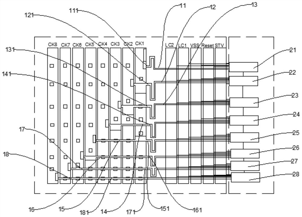
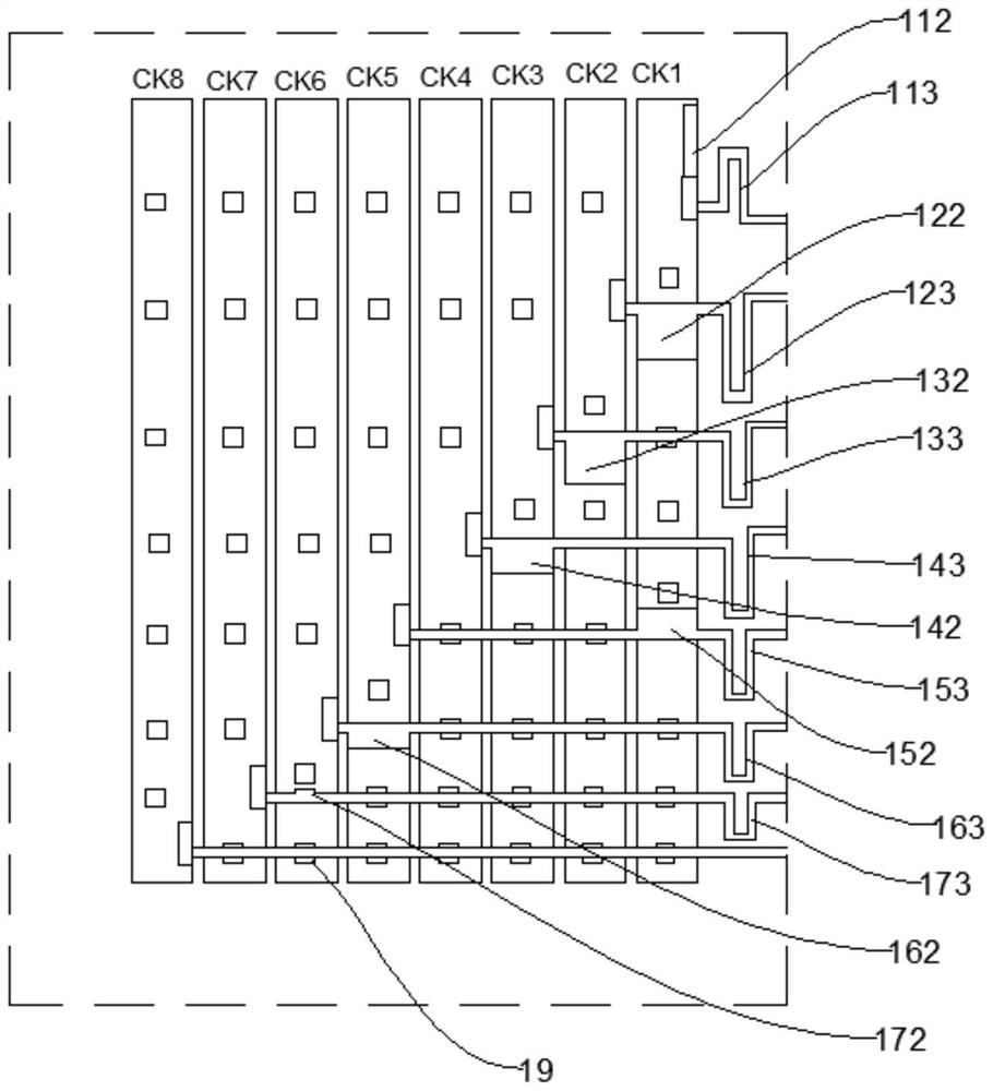
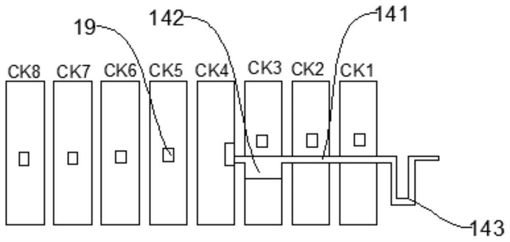
[0060] See figure 1 , figure 1 It is a structural diagram of a gate driving circuit according to the first embodiment. This embodiment provides a gate driving circuit, which includes a plurality of cascaded shift register units, n clock signal lines and control lines. The shift register unit has a clock signal terminal, and each shift register unit is correspondingly connected to a clock signal line through a connection line. Specifically, the connection line includes a conduction section, the first end of the conduction section is connected to the clock signal line, the second end of the conduction section is connected to the clock signal end of the shift register unit, the clock signal is transmitted to the shift register unit through the conduction section, n is a positive integer greater than 1, such as 2, 3, 4, 5, and 6.

[0061] Here, a plurality of shift register units can be arranged in sequence along the first direction, each shift register unit is a first-level ou...

Embodiment 2

[0094] see Image 6 , Image 6 It is a schematic structural diagram of a display panel according to the second embodiment. In the second embodiment, a display panel is also provided.

[0095] The display panel includes an effective display area 200 and a non-display area, the non-display area includes a gate drive circuit 100, the effective display area 200 includes a plurality of scan lines 300, and the gate drive circuit 100 includes a plurality of shift register units , the output end of any shift register unit provides a gate driving signal for at least one scan line 300 . Since the display panel of this embodiment has the gate driving circuit in the above embodiment, it has all the beneficial effects of the above gate driving circuit, which will not be repeated here.

[0096] In addition, the terms "first" and "second" are only used for descriptive purposes, and should not be construed as indicating or implying relative importance or implying the number of indicated te...


PUM


Abstract

The invention relates to a gate drive circuit and a display panel. The gate drive circuit comprises a plurality of cascaded shift register units, a plurality of gate drive units and a control circuit, wherein the shift register units are provided with clock signal ends; n clock signal lines, each shift register unit is correspondingly connected to one clock signal line through a connecting line, and the connecting line comprises a conduction section; the at least one connecting line further comprises a capacitance adjusting section which is electrically connected with the conduction section, the capacitance adjusting section is used for adjusting coupling capacitance between the corresponding clock signal line and the conduction section, and the capacitance adjusting section is stacked on the at least one clock signal line opposite to the conduction section connected with the capacitance adjusting section; the resistance adjusting section is electrically connected with the conduction section, and the resistance adjusting section is used for adjusting the impedance between the corresponding clock signal line and the clock signal end of the shifting register unit. According to the invention, the load difference of different clock signals can be effectively reduced, so that the display effect of the display interface is improved.

Description

technical field [0001] The present application belongs to the field of display technology, and in particular relates to a gate driving circuit and a display panel. Background technique [0002] GDL technology (Gate Driver less) is a less gate driver technology. It uses the original array process of the liquid crystal display panel to make the driving circuit of the horizontal scanning line on the substrate around the display area, so that it can replace the external integrated circuit. A board (Integrated Circuit, IC) is used to complete the driving of the horizontal scan lines. GDL technology can reduce the bonding process of external IC, which is beneficial to increase production capacity and reduce product cost, and can make liquid crystal display panels more suitable for making narrow-bezel or bezel-less display products. [0003] However, the higher the resolution of the liquid crystal display, the more clock signal lines of the gate drive circuit are required. Each s...

Claims


Application Information

Patent Timeline
IPC IPC(8): G09G3/36
CPCG09G3/3674
Inventor 卢昭阳郑浩旋
Owner CHANGSHA HKC OPTOELECTRONICS CO LTD
Why Eureka
Try Eureka