Supercharge Your Innovation With Domain-Expert AI Agents!

Method for automatically detecting leakage

An automatic detection and leakage technology, which is applied in the directions of measurement, earthwork drilling and production, wellbore/well components, etc., can solve the problems that the sealing fluid cannot be detected accurately, does not appear, and affects the efficiency of swabbing operation, etc., to ensure that The effect of safe operation, improvement of work efficiency and guarantee of safety

Pending Publication Date: 2022-07-01
西安聚盛石油科技有限公司
View PDF0 Cites 0 Cited by
  • Summary
  • Abstract
  • Description
  • Claims
  • Application Information

AI Technical Summary

Problems solved by technology

[0004] A large amount of leakage will seriously affect the efficiency of swabbing, but there is no real-time monitoring method for leakage in the well, so it will seriously affect the efficiency of swabbing operations
At the same time, the current calculation of each pumping efficiency is artificially calculated roughly, so it is impossible to detect whether the seat seal fluid is accurate, so it is impossible to check in real time whether the pulling force has reached the maximum pulling force value. If the pulling force exceeds the maximum pulling force value, then There will be certain risks in the operation, making it impossible for those skilled in the art to accurately calculate the swabbing efficiency. Therefore, there is a special need for a method that can not only ensure the safety of the operation, but also improve the work efficiency as a whole.

Method used


Image

  • Method for automatically detecting leakage
  • Method for automatically detecting leakage
  • Method for automatically detecting leakage

Examples


Embodiment 1

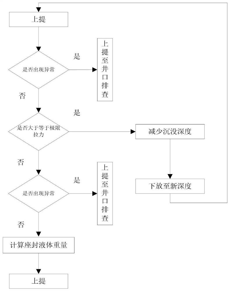
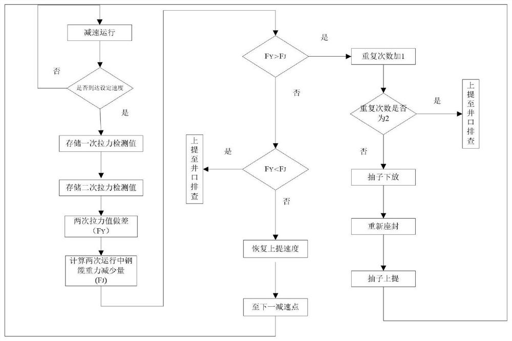
[0028] see Figure 1 to Figure 2 , an automated method for detecting leaks, comprising the following steps:

[0029] S1) During the sealing process, the tensiometer collects the lifting force of the steel cable in the process of swabbing and sealing in real time, and judges in real time whether the lifting force of the steel cable during the seat sealing is greater than the limit pulling force of the swabbing. If the lifting force of the wire rope is greater than the ultimate pulling force of the swabbing, it is judged that the calculated sunk depth is wrong, the sunk depth should be reduced, and the lifting force should be re-raised; again, judge the pulling-up pulling force and the swabbing limit of the steel wire rope detected by the tensiometer. The relationship between the pulling force, until the pull-up pulling force data of the pull-out steel cable detected by the tensiometer is less than the ultimate pulling force of the swabbing, find out the correct subsidence depth...


PUM


Abstract

The invention discloses a method for automatically detecting leakage, which comprises the following steps of: S1) collecting the lifting force applied to a steel cable in a swabbing and setting process in real time, judging whether the lifting force applied to the swab steel cable in the setting process is greater than the ultimate pulling force of swabbing or not in real time, finding out a correct sinking depth, implementing safe and correct swabbing and setting, and judging whether the lifting force applied to the swab steel cable is greater than the ultimate pulling force of swabbing; the total weight of the setting liquid is calculated according to the final sinking depth; and S2) after setting, detecting two adjacent tension values of the puller steel cable under constant-speed movement by utilizing a plurality of tension detection points arranged in the whole puller steel cable lifting process and at a constant-speed operation stage of the puller steel cable after setting, performing difference processing on the two adjacent tension values, comparing whether the tension difference is consistent with the reduced gravity of the lifting steel cable, and if so, judging whether the pulling force difference is consistent with the reduced gravity of the lifting steel cable. If yes, no leakage occurs; if so, lifting to a wellhead for checking; if yes, it is judged that leakage occurs. By measuring the correct sinking depth, the safety of swabbing operation is ensured, and meanwhile, the overall swabbing efficiency is indirectly improved.

Description

technical field [0001] The invention relates to a swab detection method, in particular to a method for automatic leakage detection. Background technique [0002] Swabbing and draining or swabbing and spurting are the basic techniques commonly used in oil and gas wells and are widely used in major oil and gas fields. Swabbing is to use a special pump to go down into the well through the wire rope and move up and down repeatedly. When the pump is lifted up, the liquid above the pump is discharged from the wellhead. At the same time, the low pressure generated by the lower part of the pump is used to continuously replenish the liquid in the oil layer into the well. The oil and gas wells can resume normal production until the fluid in the well is drained. [0003] In the process of swabbing, it is not only necessary to ensure the safety of swabbing, but also to improve work efficiency. The smaller the pumping efficiency, the longer the time it takes to drain the effusion; othe...

Claims


Application Information

Patent Timeline
Patent Type & Authority Applications(China)
IPC IPC(8): E21B47/10E21B47/04
CPCE21B47/10E21B47/04
Inventor 孙庚寅胡凯
Owner 西安聚盛石油科技有限公司
Features
  • R&D
  • Intellectual Property
  • Life Sciences
  • Materials
  • Tech Scout
  • Unparalleled Data Quality
  • Higher Quality Content
  • 60% Fewer Hallucinations
Learn More