Television display and positioning adjustment method

A display and TV technology, which is applied in the field of TV, can solve the problems such as poor positioning and adjustment of TV display, and achieve the effect of improving operation convenience, easy disassembly and use, and improving viewing comfort

Pending Publication Date: 2022-07-01
TAIZHOU HUIJIN ELECTRONIC CO LTD
View PDF9 Cites 1 Cited by
  • Summary
  • Abstract
  • Description
  • Claims
  • Application Information

AI Technical Summary

Problems solved by technology

[0005] Aiming at the deficiencies of the prior art, the present invention provides a TV display and a positioning adjustment method, which solves the problem of poor positioning and adjustment of the TV display

Method used


Image

  • Television display and positioning adjustment method
  • Television display and positioning adjustment method
  • Television display and positioning adjustment method

Examples


Embodiment 1

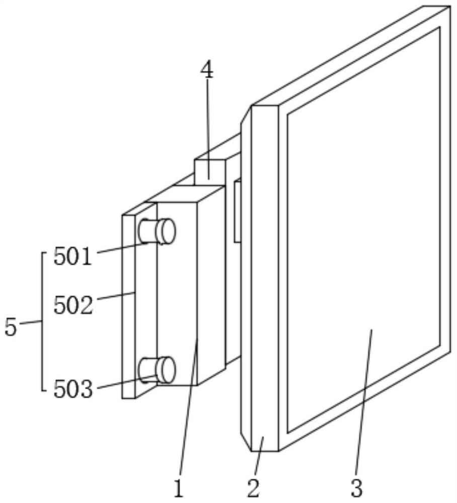
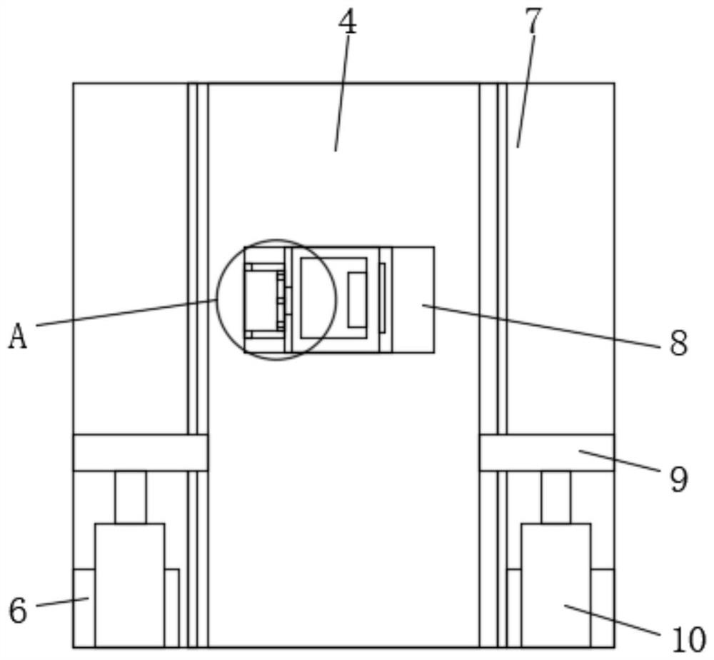
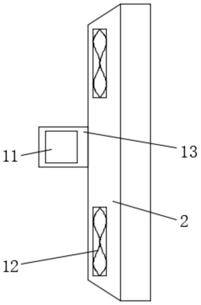
[0032] like Figure 1-6 As shown, the embodiment of the present invention provides a TV display, comprising a side recessed frame 1 and a TV casing 2, the front end of the TV casing 2 is provided with a display 3, the inner and upper ends of the TV casing 2 are provided with a cooling fan 12, and the TV casing 2 is provided with a cooling fan 12. The upper and lower ends of the rear end of 2 are provided with heat dissipation holes 14. The heat dissipation holes 14 are provided with a plurality of and are arranged at equal intervals. The interior of the heat dissipation holes 14 is provided with a dustproof net 15. The heat dissipation fan 12 is used to dissipate heat in the TV casing 2. In order to protect the display 3 from heat dissipation, an insert block 13 is provided in the middle of the rear end of the TV case 2, the two ends of the insert block 13 are provided with positioning grooves 11, and the left and right ends of the side recessed frame 1 are provided with mounti...

Embodiment 2

[0036] A positioning adjustment method for a TV display, characterized in that it comprises the following positioning adjustment steps:

[0037] S1, contact the side recessed frame 1 with the wall through the mounting plate 502 at the installation structure 5 at the left and right ends, and connect the side recessed frame 1 with the wall through the mounting member 503 in the installation hole 501, so as to locate and use the side recessed frame 1;

[0038] S2. Insert the plug 13 at the rear end of the TV shell 2 into the slot 17 of the turret 25. Before the plug 13 is inserted, move the positioning block 18 from the slot 17 to the opening of the port 22 by pulling the pull plate 21. Internally, when the insert block 13 is inserted into the slot 17, the spring 20 at the rebound plate 24 in the limiting cylinder 19 generates a rebound force, and the connecting rod 23 acts on the pull plate 21 to insert the positioning block 18 into the insert. In the positioning groove 11 at th...


PUM


Abstract

The invention provides a television display and a positioning adjustment method, and relates to the technical field of televisions. The television display comprises a side concave frame and a television shell, a display body is arranged at the front end of the television shell, an insertion block is arranged in the middle of the rear end of the television shell, a groove is formed in the front end of the side concave frame, a lifting frame is arranged in the groove, and moving grooves are formed in the left end and the right end of the interior of the side concave frame and correspond to the groove. An electric push rod is arranged at the lower end of the interior of the moving groove, a supporting groove frame is arranged in the middle of the front end of the lifting frame, a rotating groove is formed in the middle of the front end of the supporting groove frame, a rotating frame is arranged in the rotating groove, and a placement groove is formed in the left end of the interior of the supporting groove frame in a penetrating mode relative to the rotating groove; a motor is arranged at the left end of the interior of the containing groove, a motor shaft extends from one end of the motor, and one end of the motor shaft is connected with the rotating frame. Through the equipment, positioning adjustment can be effectively carried out for use.

Description

technical field [0001] The invention relates to the technical field of televisions, in particular to a television display and a positioning adjustment method. Background technique [0002] A TV is a device that uses electronic technology to transmit active images and audio signals according to the visual persistence characteristics and visual psychology of the human eye, that is, a TV receiver. It is also an important broadcast and video communication tool. The basic system of the TV consists of three parts: camera, transmission and development. [0003] At this stage, there are still some deficiencies in the use of TV monitors, which cannot be used for adjustment and positioning effectively, and the operation effect is not good. In contrast, the present invention can effectively realize convenient positioning and use, improve the use effect of positioning adjustment, and reduce the operation intensity. . SUMMARY OF THE INVENTION [0004] (1) Technical problems solved ...

Claims


Application Information

Patent Timeline
Patent Type & Authority Applications(China)
IPC IPC(8): F16M11/04F16M11/08F16M11/18F16M13/02
CPCF16M11/04F16M11/046F16M11/08F16M11/18F16M13/02
Inventor 朱宏张北涛
Owner TAIZHOU HUIJIN ELECTRONIC CO LTD
Why Eureka
Try Eureka