Novel submersible centripetal pump device

A centripetal pump, a new type of technology, applied to pump devices, components of pumping devices for elastic fluids, pumps, etc., can solve the problems of reduced efficiency, low efficiency, and the discharged liquid easily contains air or foam, etc. The effect of pressure and high lift

Pending Publication Date: 2022-07-08
WUHAN UNIV OF TECH
View PDF8 Cites 0 Cited by
  • Summary
  • Abstract
  • Description
  • Claims
  • Application Information

AI Technical Summary

Problems solved by technology

However, there are some defects in the existing centrifugal pumps: First, the overall working efficiency is low, and its theoretical basis has congenital defects. The efficiency of domestic IS single-suction centrifugal pumps is generally below 60%, while the efficiency of multi-stage centrifugal pumps is even lower. ; Second, the nonlinear flow field leads to difficulties in the calculation of physical quantities such as flow and head and impeller design; third, it is suitable for large flow fluids, and the efficiency is low and limited for fluids with small flow and large pressure heads; fourth, In case of incomplete design or improper operation by the operator, the discharged liquid may easily contain air or foam
However, the defects of existing centripetal pumps are that when riveting, the riveting is not firm enough to cause problems such as poor fit between the pump body and the pump cover, so that there is a gap between the pump body and the pump cover, resulting in a reduction in the delivery capacity and generation of transport fluid. Foam, emulsification and other phenomena; secondly, during the process of fluid delivery by the centripetal pump, the fluid movement direction is changed from tangential to vertical axial direction, resulting in large energy loss and low efficiency

Method used


Image

  • Novel submersible centripetal pump device
  • Novel submersible centripetal pump device
  • Novel submersible centripetal pump device

Examples


Embodiment Construction

[0021] In order to make the purposes, technical solutions and advantages of the embodiments of the present application more clear, the technical solutions in the embodiments of the present application will be described clearly and completely below with reference to the drawings in the embodiments of the present application. Obviously, the described embodiments It is a part of the embodiments of the present application, but not all of the embodiments. The components of the embodiments of the present application generally described and illustrated in the drawings herein may be arranged and designed in a variety of different configurations.

[0022] Thus, the following detailed description of the embodiments of the application provided in the accompanying drawings is not intended to limit the scope of the application as claimed, but is merely representative of selected embodiments of the application. Based on the embodiments in this application, all other embodiments obtained by ...


PUM


Abstract

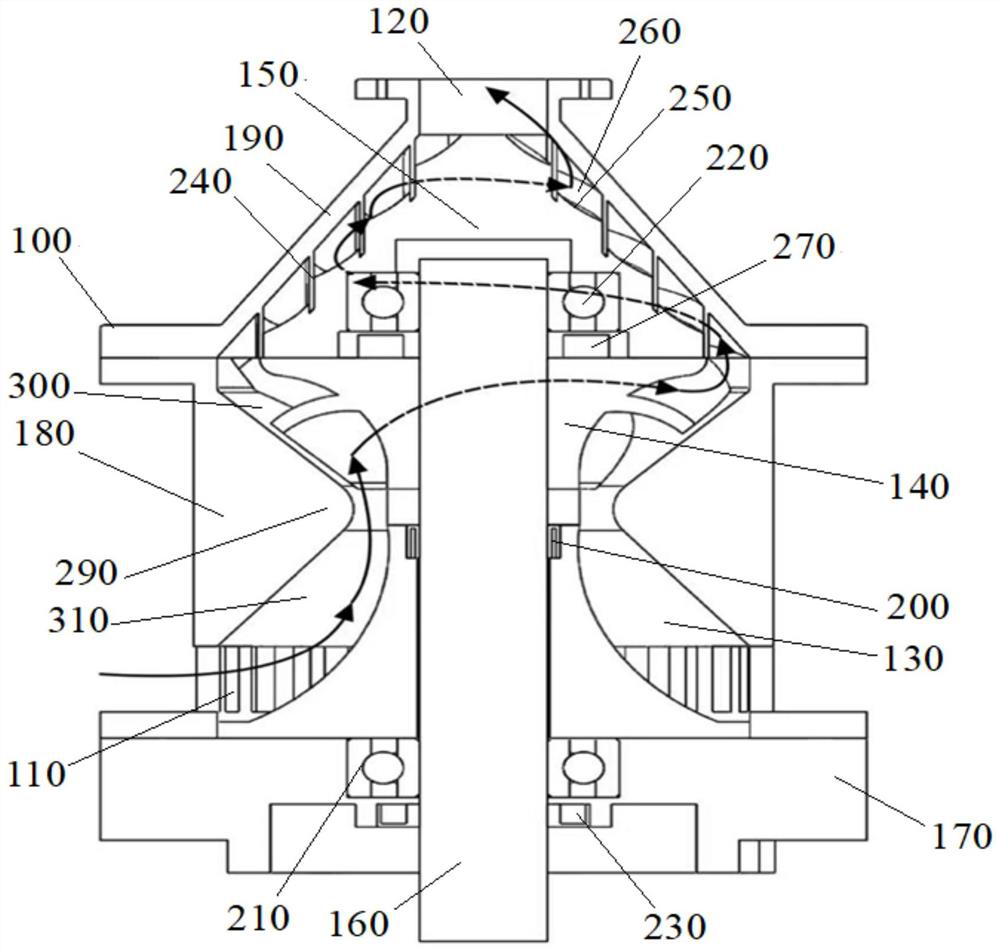
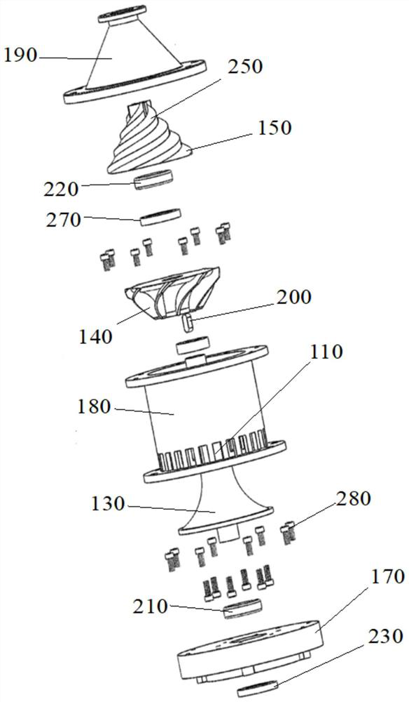
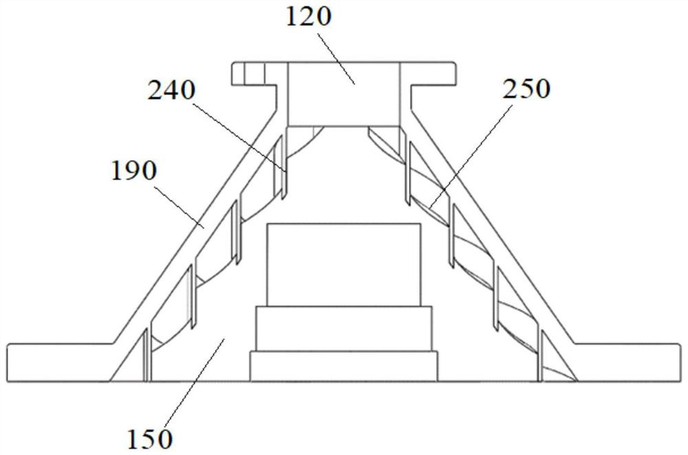
The invention discloses a novel submersible centripetal pump device and relates to the field of centripetal pumps. The novel submersible centripetal pump device comprises a centripetal pump body, a plurality of inlets are formed in the peripheral wall of one end of the centripetal pump body at intervals in the circumferential direction of the centripetal pump body, an outlet is formed in the end face of the other end of the centripetal pump body, and a front guide vane, a rotatable impeller and a rear guide vane are sequentially arranged in the centripetal pump body in the axial direction of the centripetal pump body. The end face of the end, away from the outlet, of the centripetal pump body is connected with a pump shaft coaxially connected with the impeller, and the front guide vane is used for guiding fluid entering the inlets in the radial direction of the centripetal pump body to flow through the impeller in the axial direction of the centripetal pump body. The rear guide vane is used for guiding fluid flowing through the impeller in the axial direction of the centripetal pump body to move towards the axis of the centripetal pump body in the spiral direction and be discharged from the outlet. According to the novel submersible centripetal pump device, the pressure of fluid at the outlet can be improved, and therefore higher lift can be achieved under the condition of low flow.

Description

technical field [0001] The present application relates to the field of centripetal pumps, in particular, to a novel submersible centripetal pump device. Background technique [0002] Centrifugal pump is currently the most widely used, the largest amount of a pump device with the highest output value. However, the existing centrifugal pumps have some defects: First, the overall working efficiency is low, and its theoretical basis has congenital defects. The efficiency of domestic IS single-suction centrifugal pumps is generally below 60%, while the efficiency of multi-stage centrifugal pumps is even lower. ; Second, the nonlinear flow field makes it difficult to calculate the physical quantities such as flow and head, and to design the impeller; third, it is suitable for large-flow fluids, but it is less efficient and limited for fluids that supply small flow and large pressure head; Fourth, In the case of incomplete design or improper operation by the operator, the discharg...

Claims


Application Information

Patent Timeline
IPC IPC(8): F04D13/08F04D29/00F04D29/046F04D29/12F04D29/24F04D29/44
CPCF04D13/08F04D29/00F04D29/046F04D29/126F04D29/242F04D29/448
Inventor 徐辰柳蓓韩承宇汤旭晶吴莹明敬哲何泽华薄宇泽
Owner WUHAN UNIV OF TECH
Why Eureka
Try Eureka