Air inlet pipe for liquid accumulator and liquid accumulator

A liquid accumulator and air intake pipe technology, applied in the field of compressors, can solve the problems of blockage of compressor suction, limited size design, inability to change, etc., and achieve the effect of increasing the flow area and high flow demand.

Pending Publication Date: 2022-07-08
SHANGHAI HITACHI ELECTRICAL APPLIANCES CO LTD
View PDF0 Cites 0 Cited by
  • Summary
  • Abstract
  • Description
  • Claims
  • Application Information

AI Technical Summary

Problems solved by technology

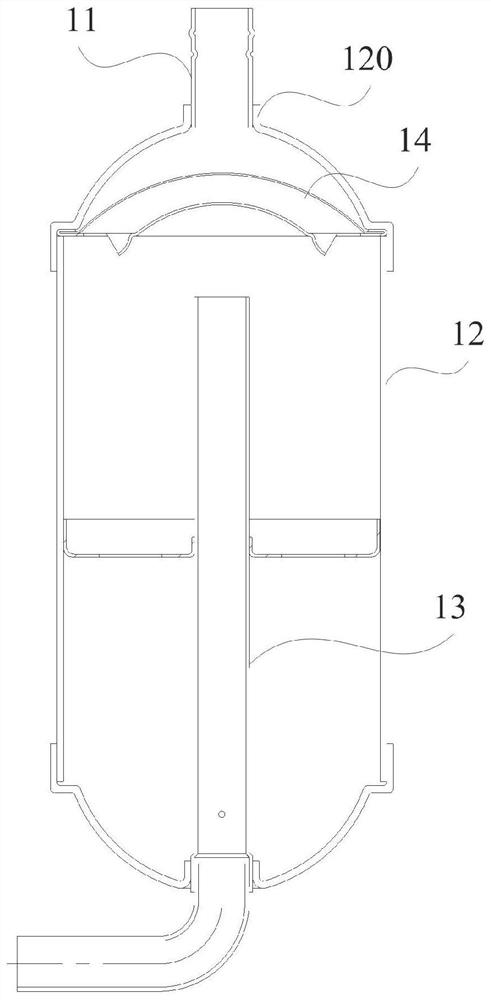
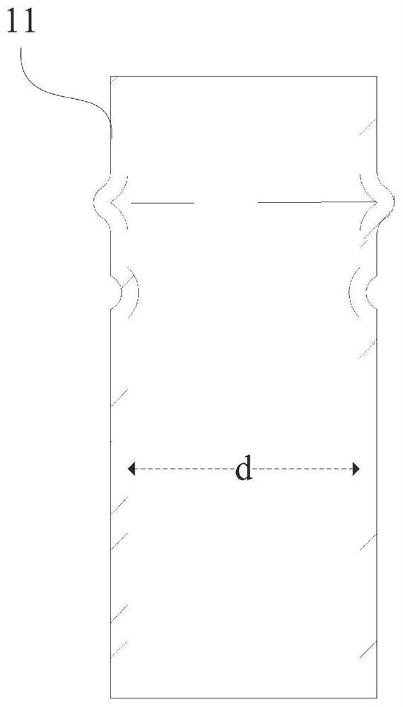
The diameter d of the intake pipe 11 is limited by the size design of the air inlet 120 of the cylinder 12 and cannot be changed, resulting in that the flow area of ​​the intake pipe 11 cannot be adjusted according to the demand
[0004] In addition, although the existing liquid reservoir is provided with a filter 14 between the intake pipe 11 and the air guide pipe 13, the filter screen 14 can only play a preliminary filtering role, and some fine impurity particles will still enter the air guide pipe with the flow of refrigerant gas. 13. Cause compressor suction blockage

Method used


Image

  • Air inlet pipe for liquid accumulator and liquid accumulator
  • Air inlet pipe for liquid accumulator and liquid accumulator
  • Air inlet pipe for liquid accumulator and liquid accumulator

Examples


Embodiment Construction

[0027] Example embodiments will now be described more fully with reference to the accompanying drawings. However, example embodiments can be embodied in various forms and should not be construed as limited to the embodiments set forth herein. Rather, these embodiments are provided so that this disclosure will be thorough and complete, and will fully convey the concept of example embodiments to those skilled in the art. Furthermore, the drawings are merely schematic illustrations of the invention and are not necessarily drawn to scale. The same reference numerals in the drawings denote the same or similar parts, and thus their repeated descriptions will be omitted.

[0028] "First," "second," and similar words used in the detailed description do not denote any order, quantity, or importance, but are merely used to distinguish the different components. It should be noted that the embodiments of the present invention and features in different embodiments may be combined with ea...


PUM


Abstract

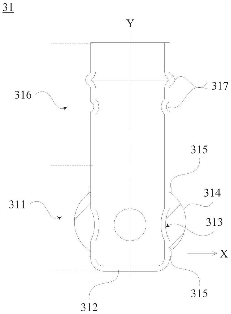
The invention relates to the technical field of compressors, and provides an air inlet pipe for a liquid accumulator and the liquid accumulator. The air inlet pipe for the liquid storage device is connected with an air inlet of the liquid storage device in a sealed mode, the air inlet pipe for the liquid storage device comprises a first pipe section extending into the liquid storage device from the air inlet, a port of the first pipe section is sealed, and a through hole is formed in the pipe wall of the first pipe section. A filter screen surrounding and covering the through hole is arranged on the outer pipe wall of the first pipe section, and the filter screen protrudes away from the central shaft of the air inlet pipe for the liquid accumulator. The end opening of the first pipe section is sealed, the through hole is formed in the pipe wall, and the filter screen covers the through hole in a surrounding mode, so that refrigerant gas passes through the through hole in the pipe wall, is filtered through the filter screen and then flows into the barrel of the liquid storage device, and dual effective filtration of impurity particles in the refrigerant gas is achieved through the sealed end opening and the filter screen covering the through hole; and the circulation area of refrigerant gas can be increased.

Description

technical field [0001] The present invention relates to the technical field of compressors, and in particular, to an air intake pipe for a liquid accumulator and a liquid accumulator including the air intake pipe for the liquid accumulator. Background technique [0002] The accumulator is an important part in the air conditioning pipeline, installed on the suction side of the compressor, and plays the role of gas-liquid separation and refrigerant buffering. [0003] figure 1 shows the structure of the existing reservoir, figure 2 The structure of the intake pipe of the existing accumulator is shown, combined with figure 1 and figure 2 As shown, the refrigerant gas flows from the intake pipe 11 into the cylinder 12 of the existing accumulator, and is then sucked into the compressor through the air conduit 13 . The diameter d of the intake pipe 11 is limited by the size design of the intake port 120 of the cylinder 12 and cannot be changed, so that the flow area of ​​the...

Claims


Application Information

Patent Timeline
Patent Type & Authority Applications(China)
IPC IPC(8): F25B43/00
CPCF25B43/006Y02E60/16
Inventor 周易张鼎
Owner SHANGHAI HITACHI ELECTRICAL APPLIANCES CO LTD
Why Eureka
Try Eureka