
Dip pipe for RH vacuum refining device

A technology of vacuum refining and dipping tubes, which is applied in the field of dipping tubes, can solve the problems of increasing the structural size of dipping tubes, and achieve the effects of reducing the amount of cold steel adhesion, increasing the circulation flow rate, and increasing the flow area

Active Publication Date: 2014-06-04
NORTHEASTERN UNIV
View PDF1 Cites 17 Cited by
  • Summary
  • Abstract
  • Description
  • Claims
  • Application Information

AI Technical Summary

Problems solved by technology

[0020] (3) The dipping tube needs to be inserted into the ladle when it is working, and increasing the structural size of the dipping tube is severely restricted by the size of the ladle

Method used


Image

  • Dip pipe for RH vacuum refining device
  • Dip pipe for RH vacuum refining device
  • Dip pipe for RH vacuum refining device

Examples


Embodiment Construction

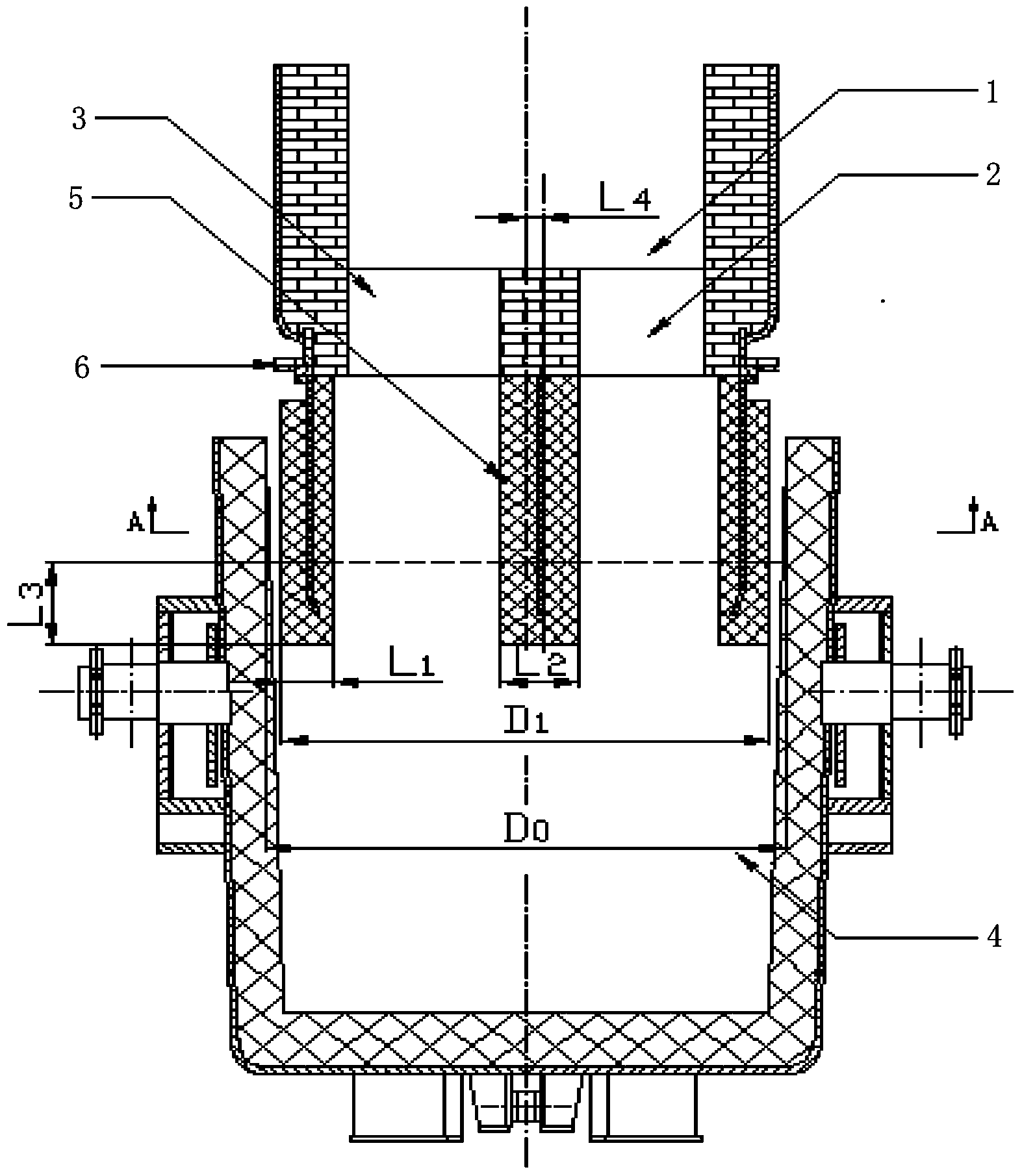
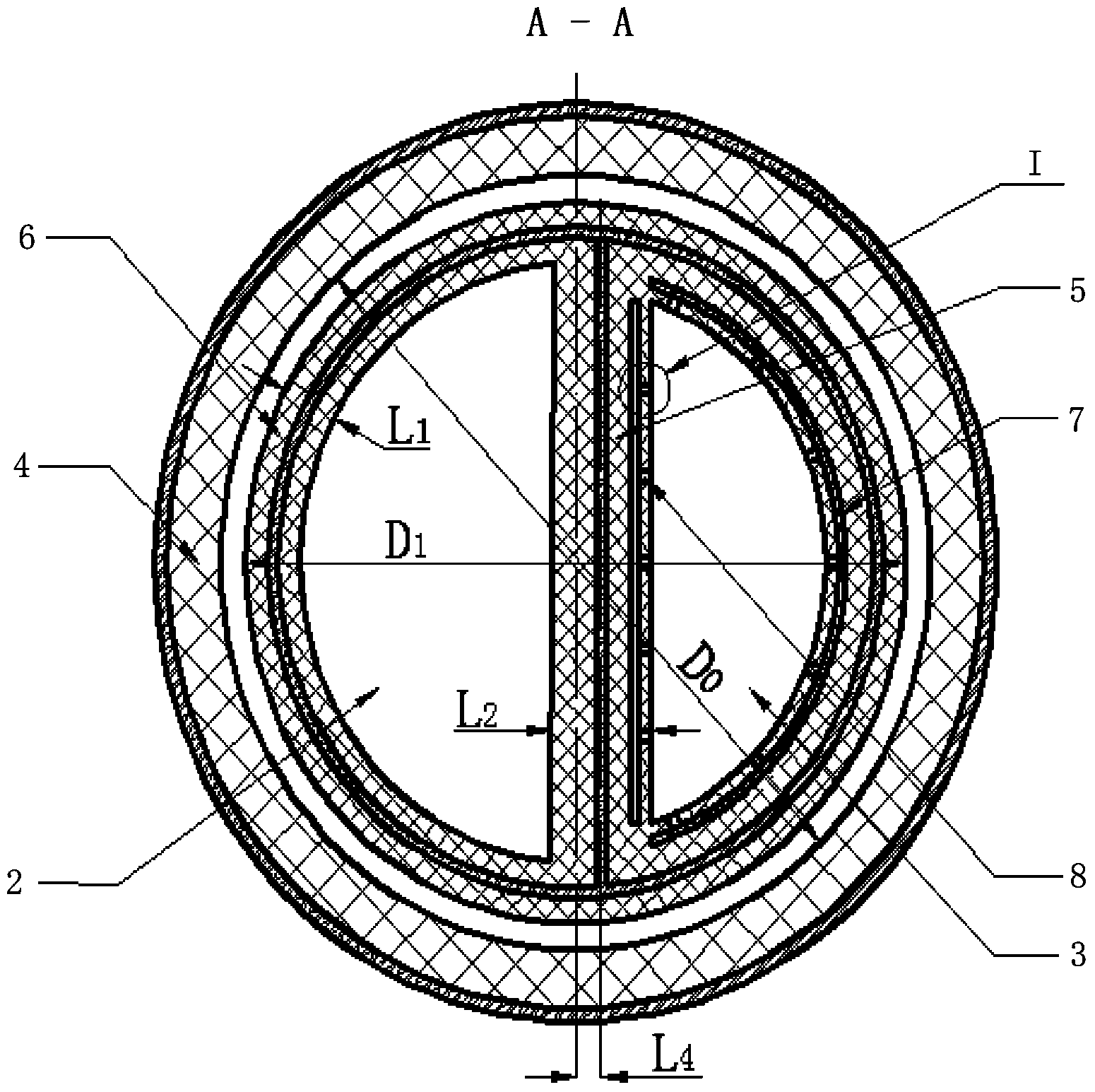
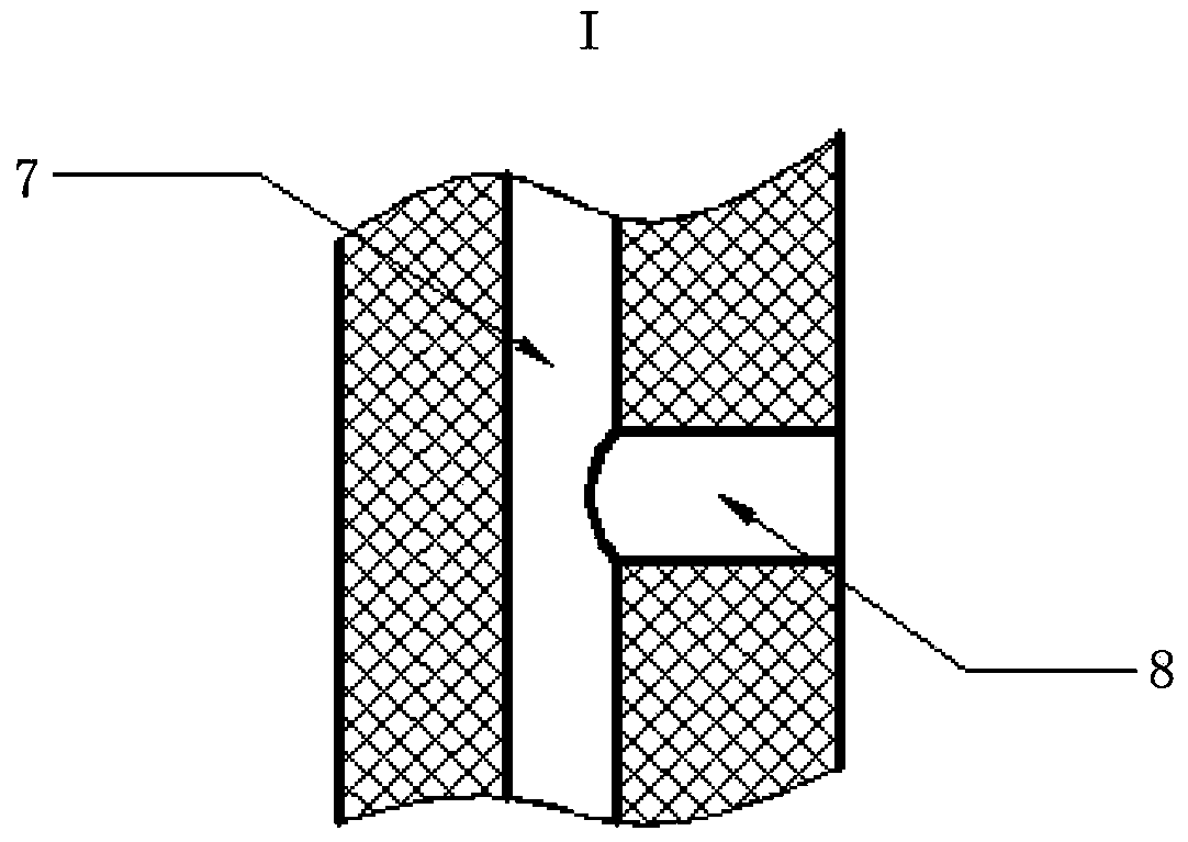
[0038] The integrated double-arc dip tube used in the RH vacuum refining device completed by the present invention has been applied on the 180t RH vacuum refining device, and the specific structure is as follows figure 1 , figure 2 and image 3 shown. The immersion tube is a straight cylindrical one-piece structure, and is divided into an arc-shaped ascending tube 2 and an arc-shaped downcomer 3 by an intermediate partition wall 5. The downcomer 3 is composed of another part of the arc-shaped inner wall of the dipping tube and the other side wall of the middle partition wall 5. The lower part of the riser tube 2 is provided with a lifting gas blowing conduit 7, and a lifting gas blowing conduit 7 is provided. There is a lift gas outlet, and the lift blow-in conduit 7 communicates with the blow port 8 . The upper ends of the ascending pipe and the descending pipe are provided with welded and fixed flanges 6 to be fixed with the vacuum chamber 1 . In order to cooperate with...


PUM


Abstract

The invention discloses a dip pipe for an RH vacuum refining device. The dip pipe comprises an ascension pipe and a descending pipe and is divided into the arc-shaped ascension pipe and the arc-shaped descending pipe by a middle partition wall, wherein a lifting gas blowing-in guide pipe is arranged at the lower part of the ascension pipe, a lifting gas outlet is formed in the lifting gas blowing-in guide pipe, and the dip pipe formed by the ascension pipe and the descending pipe is fixed at the lower end of a vacuum chamber through a flange welded on the dip pipe. As the dip pipe with the structure fully utilizes the space of the bottom of the vacuum chamber, a gap between the ascension pipe and the descending pipe of a conventional dip pipe, which is generated due to a refractory material, is omitted, the flow area of dip pipe molten steel is enlarged, and therefore, the circular flow of a vacuum circulating gas stripping unit RH can be obviously increased.

Description

technical field [0001] The invention relates to the field of external refining of molten steel, in particular to a dip tube used in an RH vacuum refining device. Background technique [0002] In the field of refining outside the furnace, the vacuum refining equipment for molten steel mainly includes RH, VD and other devices. RH refers to an integral or split vacuum chamber. When processing molten steel, all metallurgical reactions are carried out in the vacuum chamber. The bottom of the RH is two circular dipping tubes, which are the ascending pipe and the descending pipe. The upper part is connected The hot bending pipe is connected with the vacuum system, and each part is combined into a set of vacuum refining device. [0003] The entire metallurgical reaction process of RH is carried out in a vacuum chamber lined with refractory bricks. When the dipping tube is inserted into the molten steel, the vacuum chamber is started to be evacuated. At this time, under the action ...

Claims


Application Information

Patent Timeline
IPC IPC(8): C21C7/10
Inventor 邹宗树许涛
Owner NORTHEASTERN UNIV
Learn More