Gas circuit axial grading type dual-fuel nozzle

A staged, dual-fuel technology, applied in combustion chambers, combustion methods, combustion equipment, etc., can solve the problem of deteriorating working environment of gas turbine blades, lower uniformity of temperature field at the outlet of combustion chamber, poor mixing of pyrolysis gas and air, etc. problem, to achieve the effect of increasing the radial size, shortening the flame, and strengthening the combustion

Inactive Publication Date: 2013-06-26
HARBIN ENG UNIV
View PDF6 Cites 17 Cited by
  • Summary
  • Abstract
  • Description
  • Claims
  • Application Information

AI Technical Summary

Problems solved by technology

[0003] In order to ensure the same temperature at the exit of the combustion chamber, the mass flow rate of the pyrolysis gas must be much greater than the mass flow rate of the fuel oil. If the flow rate is too high, the mixture of the pyrolysis gas and air will be poor, and the flow field will be difficult to organize, which will easily cause the flame to elongate and the exit of the combustion chamber The uniformity of the temperature field is reduced, which deteriorates the working environment of the gas turbine blades
The patent "Dual fuel nozzle" (application number US19990470592) and the patent "DUAL FUEL NOZZLE" (application number JP19980367255) increase the flow area of ​​the gas by increasing the airflow channel in the radial direction, and the modification of the combustion chamber is relatively large

Method used


Image

  • Gas circuit axial grading type dual-fuel nozzle
  • Gas circuit axial grading type dual-fuel nozzle
  • Gas circuit axial grading type dual-fuel nozzle

Examples


Embodiment Construction

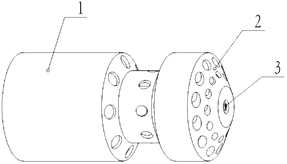
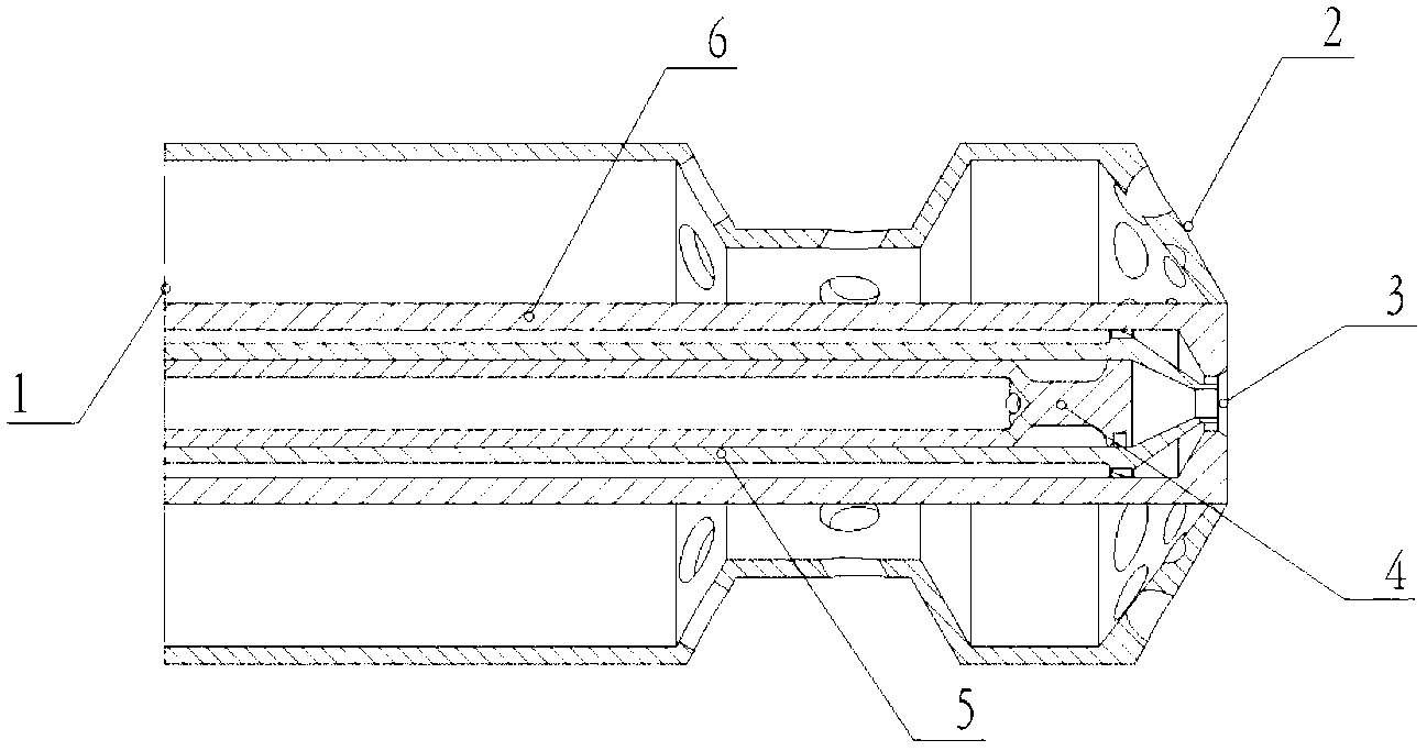
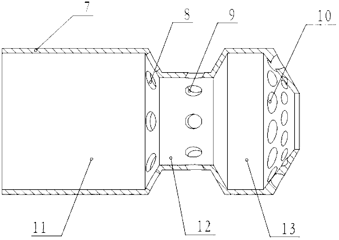
[0016] The present invention is described in more detail below in conjunction with accompanying drawing example:

[0017] combine Figure 1~3 , an air path axially graded dual fuel nozzle 1 of the present invention includes an outer wall of the gas path 7, a main oil path pipeline 6, an auxiliary oil path pipeline 5, and an auxiliary oil path swirler 4, and the gas path 2 adopts an axially graded arrangement , the oil circuit 3 pipeline is installed in the middle of the gas circuit 2 and forms a gas circuit cavity between the outer wall of the gas circuit 7, and the gas circuit 2 is divided into a gas circuit front cavity 11 and a gas circuit rear cavity 13 through the gas circuit throat part 12, and the gas fuel It is ejected through the jet holes 8, 9, 10 of the primary, throat and secondary air passages, and the liquid fuel is injected into the combustion chamber through the main and auxiliary oil passages 6, 5, and water can be injected back through the air passage during ...


PUM


Abstract

The invention aims to provide a gas circuit axial grading type dual-fuel nozzle which comprises a gas circuit outer wall and a main oil circuit wall arranged inside the gas circuit outer wall. An auxiliary oil circuit wall is arranged inside the main oil circuit wall. A main oil circuit channel is formed between the main oil circuit wall and the auxiliary oil circuit wall. An auxiliary oil circuit channel is formed inside the auxiliary oil circuit wall. A gas circuit is formed between the gas circuit outer wall and the main oil circuit wall. The gas circuit comprises a gas circuit front cavity, a gas circuit laryngeal and a gas circuit rear cavity in sequential communication. A first level gas circuit gas ejection hole is formed in a position, arranged on the gas circuit front cavity, of the gas circuit outer wall. A laryngeal gas ejection hole is formed in the gas circuit laryngeal. A second level gas circuit gas ejection hole is formed in the gas circuit rear cavity. Due to the fact that a gas circuit axial grading type structure is adopted, the gas circuit axial grading type dual-fuel nozzle has the advantages of reducing the radial size of the nozzle, simultaneously increasing gas circuit flow area, enhancing mixing of fuel and air, strengthening burning, shortening flame, and simultaneously not burning the wall surface of a flame tube. When liquid fuel is burned, water vapor reinjection is conducted by the gas circuit.

Description

technical field [0001] The invention relates to a gas turbine, in particular to a fuel nozzle of the gas turbine. Background technique [0002] Gas turbines are widely used in aviation, shipping, electric power, petroleum and many other industrial fields due to their advantages such as simple structure, high single-unit power, small weight and size, and good maneuverability. Therefore, the technical transformation and performance optimization of conventional gas turbine application technology has become an important topic to solve the energy crisis and environmental pollution problems. The chemical regenerative cycle is a new type of advanced cycle method, which mainly uses the low-end waste heat of the exhaust gas of the gas turbine to generate superheated steam, and under the action of the catalyst, the fuel-steam is cracked to generate gaseous fuels such as methane, hydrogen and carbon monoxide. Studies have shown that if diesel oil is completely cracked, the heat genera...

Claims


Application Information

Patent Timeline
Patent Type & Authority Applications(China)
IPC IPC(8): F23R3/36
Inventor 潘刚郑洪涛杨洪磊和宏宾胡晓明陈曦张智博刘倩潘福敏
Owner HARBIN ENG UNIV
Why Eureka
Try Eureka