Rotor structure, motor and compressor

一种转子结构、转子铁芯的技术,应用在转子结构,电机及压缩机领域,能够解决开孔空间有限、难以同时保证压缩机冷媒及油整体循环效率转子与转轴扭矩等问题,达到提高磁场强度、确保固定连接、降低噪音的效果

Active Publication Date: 2017-02-22
ZHUHAI GREE REFRIGERATION TECH CENT OF ENERGY SAVING & ENVIRONMENTAL PROTECTION
View PDF11 Cites 17 Cited by
  • Summary
  • Abstract
  • Description
  • Claims
  • Application Information

AI Technical Summary

Problems solved by technology

[0005] Therefore, the technical problem to be solved by the present invention is that it is difficult to simultaneously ensure the overall circulation efficiency of the compressor refrigerant and oil and the torque between the rotor and the shaft when the opening space on the rotor core is limited.

Method used


Image

  • Rotor structure, motor and compressor
  • Rotor structure, motor and compressor
  • Rotor structure, motor and compressor

Examples


Embodiment 1

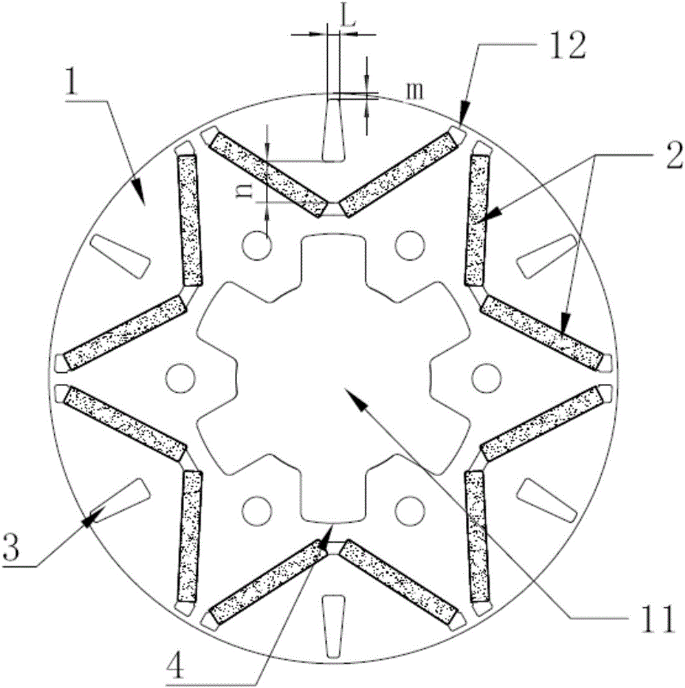
[0053] This embodiment provides a rotor structure, including a rotor core 1, a magnetic steel 2 and a limiting assembly.

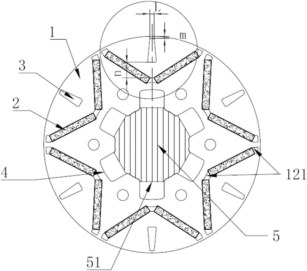
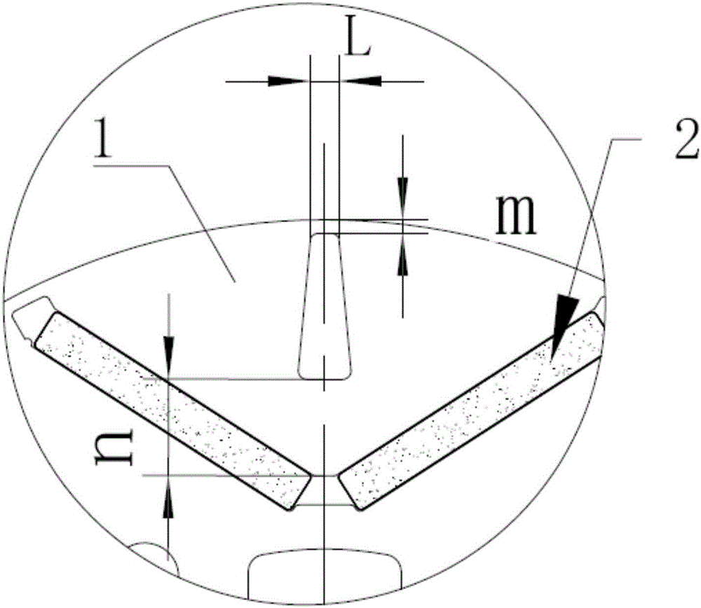
[0054] Among them, such as figure 1 As shown, the rotor core 1 is formed with a shaft hole 11 for fixed connection with the rotating shaft 5 and six magnetic steel grooves 12 along its rotation axis. The magnetic steel grooves 12 are V-shaped grooves, and the six V-shaped grooves are formed in the The outer circumference of the shaft hole 11 is symmetrically distributed, the opening of the V-shaped groove is facing away from the side of the shaft hole 11, and the bottom near the shaft hole 11 is a horizontal connection part; two polarities are set in each V-shaped groove The same and symmetrically distributed magnetic steel 2, that is, two magnetic steel 2 with the same polarity are installed on the two inclined parts of the V-shaped groove respectively, and the polarity of the magnetic steel 2 in two adjacent magnetic steel grooves 12 On the contrary, fo...

Embodiment 2

[0074] This embodiment provides a motor, including a stator and a rotor structure disposed in the inner hole of the stator, and the rotor structure is any one of the rotor structures provided in Embodiment 1.

[0075] The motor in this embodiment adopts the rotor structure in Embodiment 1, so that the flow area of ​​the inner rotor of the motor is increased, the heat dissipation speed of the motor iron core is accelerated, and the torque between the rotor and the rotating shaft 5 is ensured at the same time, and the rotation speed of the motor is reduced. Torque pulsation, reducing the noise generated by the vibration during the motor's working process.

Embodiment 3

[0077] This embodiment provides a compressor, including a motor, and the motor is any one of the motors provided in Embodiment 2.

[0078] The compressor in this embodiment adopts the motor provided in Implementation 2, so that the circulation area of ​​the compressor’s refrigerant and oil on the rotor core 1 increases, improving the overall circulation efficiency of the compressor’s refrigerant and oil, while also being able to The torque between the rotor and the rotating shaft 5 is guaranteed, the torque ripple of the motor is reduced, the vibration noise during the operation of the motor is reduced, and the service life of the compressor and the motor is improved.


PUM


Abstract

The invention discloses a rotor structure, a motor and a compressor. The rotor structure comprises a rotor iron core and magnetic steel. A shaft hole fixed connected with a revolving shaft and an even number of magnetic steel tanks are formed in the rotor iron core in a rotation axis of the rotor iron core, and magnetic steel tanks are symmetrically formed in the rotor iron core and around the outer periphery of the shaft hole; magnetic steel is installed in the magnetic steel tanks in a one-to-one correspondence mode; first through grooves are symmetrically formed in the rotor iron core and around the inner wall face of the shaft hole, extending in the axial direction and concaved in the radial direction; first through holes are formed between the first through grooves and the outer wall face of the revolving shaft. The motor includes a stator and the rotor structure arranged in the inner hole of the stator. The compressor includes the motor. The first through holes are directly formed in the shaft hole of the rotor iron core to serve as one part of the shaft hole, can increase the circulation areas of the rotor, accelerate the overall cycle efficiency of refrigerant and oil, and are beneficial to heat dissipation of the motor and the revolving shaft. At the same time, the revolving shaft is fixedly matched with the first through holes, and thus the torque between the rotor and the revolving shaft is ensured.

Description

technical field [0001] The invention belongs to the technical field of motors, and in particular relates to a rotor structure, a motor and a compressor. Background technique [0002] Permanent magnet motors use the electromagnetic induction of the magnetic field between the stator and rotor to drive the load. With the rapid development of power electronics technology, microelectronics technology, new motor control theory and rare earth permanent magnet materials, permanent magnet synchronous motors can be rapidly popularized and applied. . The motor mainly includes a stator and a rotor structure arranged in the inner hole of the stator. The stator is energized by the outside world, and the rotor rotates continuously under the action of the magnetic field generated by the stator. [0003] During the working process of the motor, excess heat is generated due to its iron loss, and the accumulation of this part of heat will eventually lead to the damage of the insulating parts ...

Claims


Application Information

Patent Timeline
Patent Type & Authority Applications(China)
IPC IPC(8): H02K1/27H02K1/32
CPCH02K1/2753H02K1/32H02K2213/03H02K1/2766H02K1/28H02K1/276
Inventor 史进飞吴曼米泽银肖勇
Owner ZHUHAI GREE REFRIGERATION TECH CENT OF ENERGY SAVING & ENVIRONMENTAL PROTECTION
Why Eureka
Try Eureka