
Anti-swing balance structure of sliding door

A balanced structure, anti-swing technology, applied in door/window fittings, building structures, buildings, etc., can solve problems such as occupying floor space, breaking guide wheels, affecting appearance, etc.

Pending Publication Date: 2022-07-12
赖莎
View PDF0 Cites 1 Cited by
  • Summary
  • Abstract
  • Description
  • Claims
  • Application Information

AI Technical Summary

Problems solved by technology

The existing sliding doors generally include upper and lower track type and upper track suspension type, in which the bearing point of the upper and lower rails is on the lower rail, the main disadvantages are: not only occupying the ground space, affecting the appearance, but also easy to accumulate dust due to the track box , and the dust is not easy to clean, it is easy to fall over and hinder the passage
The bearing point of the upper rail sliding door is on the top, and the appearance of the hanging rail sliding door makes up for the shortcomings of the upper and lower rail sliding doors. However, the hanging rail sliding door needs to install guide wheels on the ground, and the installation accuracy is high. If the installation is improper, the door body will be pushed and pulled. It is easy to get stuck in the process, and then break the guide wheel, and then cause safety hazards, especially the pocket structure where the door body is retracted into the wall is very difficult to install; in view of this, a positioning anti-swing device is designed in the upper rail , making it easy to install and widely used products has become our research direction

Method used


Image

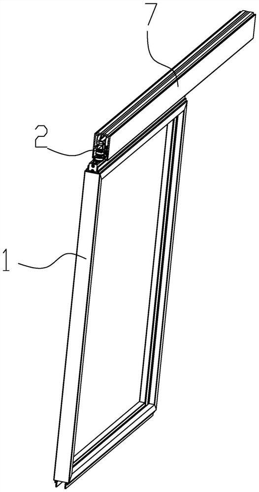
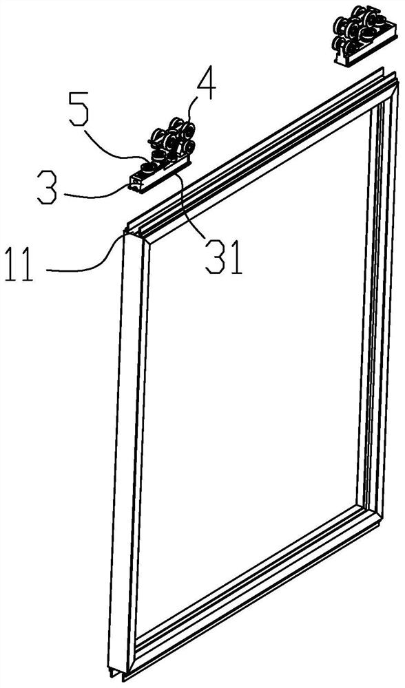
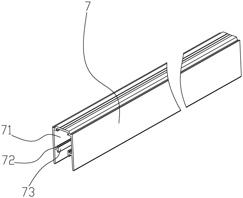
  • Anti-swing balance structure of sliding door
  • Anti-swing balance structure of sliding door
  • Anti-swing balance structure of sliding door

Examples


Embodiment Construction

[0027] The following describes in detail the embodiments of the present invention, examples of which are illustrated in the accompanying drawings, wherein the same or similar reference numerals refer to the same or similar elements or elements having the same or similar functions throughout.

[0028] In the description of the present invention, it should be noted that for orientation words, such as the terms "center", "horizontal (X)", "longitudinal (Y)", "vertical (Z)", "length", "width" ", "thickness", "top", "bottom", "front", "back", "left", "right", "vertical", "horizontal", "top", "bottom", "inside" , "outside", "clockwise", "counterclockwise" and other indications of orientation and positional relationship are based on the orientation or positional relationship shown in the accompanying drawings, only for the convenience of describing the present invention and simplifying the description, rather than indicating or implying that The device or element must have a specific...


PUM


Abstract

The anti-swing balance structure of the sliding door comprises a hanger rail device assembled on a moving part, and the hanger rail device comprises a lifting hanging box, a vertical hanging wheel set and a transverse adjusting wheel set; the vertical hanging wheel set comprises an upper pulley and a clamping pulley, and the upper pulley and the clamping pulley are arranged in a spaced mode so that a clamping space can be formed between the upper pulley and the clamping pulley. The transverse adjusting wheel set comprises an adjusting bottom plate, a positioning shaft nail and an adjustable upper wheel plate, the lifting hanging box is provided with an adjusting screw rod, and the adjusting screw rod is connected with the connector in a screwed mode so as to drive the adjusting bottom plate to move in the direction of the adjusting screw rod; a follow-up wheel shaft is arranged at the end part of the adjustable upper wheel plate, and the adjustable upper wheel plate drives the wheel body to rotate towards the outside / inside of the lifting hanging box; wheel bodies of the vertical hanging wheel set and the transverse adjusting wheel set adopt surface connecting wheels, and the edges of the surface connecting wheels are arc-shaped end surfaces. The device has the advantages of simple structure, excellent effect, convenience in assembly, reasonable design and the like; therefore, the device is a product with excellent technical and economical performance.

Description

【Technical field】 [0001] The invention mainly relates to an anti-swing balance structure for a sliding door. 【Background technique】 [0002] Sliding sliding doors are increasingly popular and used in daily life. They are widely used in bookcases, wall cabinets, living rooms, exhibition halls, sliding doors, etc., which play the role of separating space and decoration. The existing sliding doors generally include upper and lower rail type and upper rail suspension type. Among them, the upper and lower rail sliding doors are mainly supported by the lower rail. The main disadvantages are: not only the floor space is occupied, but also the appearance is affected, and the rail box is easy to accumulate dust. , and the dust is not easy to clean, and it is easy to overturn and obstruct the passage. The bearing point of the upper rail sliding door is above, and the appearance of the hanging rail sliding door fills the shortcomings of the upper and lower rail sliding doors, but the ...

Claims


Application Information

Patent Timeline
IPC IPC(8): E05D13/00E05D15/06
CPCE05D13/00E05D15/0639
Inventor 赖莎
Owner 赖莎
Learn More