Additive manufacturing method, equipment, device, storage medium and metallurgical bonding part

A technology for additive manufacturing and storage media, applied in the fields of storage media and metallurgical joints, additive manufacturing methods, devices, and equipment, it can solve the problems of poor torsion resistance and bending resistance, easy damage and failure, etc., to reduce cracking, Reduce the effect of stress concentration and solve the effect of easy damage and failure

Pending Publication Date: 2022-07-15
WUHAN POLYTECHNIC UNIVERSITY
View PDF0 Cites 0 Cited by
  • Summary
  • Abstract
  • Description
  • Claims
  • Application Information

AI Technical Summary

Problems solved by technology

[0004] The main purpose of the present invention is to provide an additive manufacturing method, equipment, device, storage medium and metallurgical combination, aiming to solve the problem of easy damage, failure, torsion resistance and bending resistance of formed parts prepared by laser cladding technology when they are put into use Technical issues with poor performance

Method used


Image

  • Additive manufacturing method, equipment, device, storage medium and metallurgical bonding part
  • Additive manufacturing method, equipment, device, storage medium and metallurgical bonding part
  • Additive manufacturing method, equipment, device, storage medium and metallurgical bonding part

Examples


no. 1 example

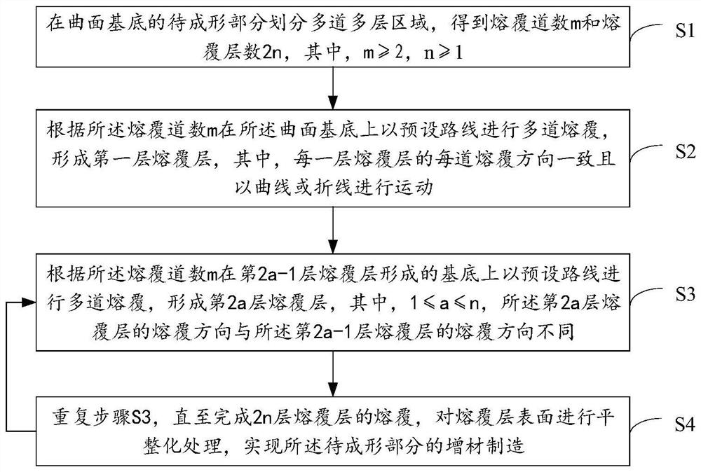
[0057] Based on the above-mentioned first embodiment, the additive manufacturing method of this embodiment further includes:

[0058] Step S4: After the cladding of the 2n-layer cladding layer is completed, the surface of the cladding layer is flattened to realize the additive manufacturing of the part to be formed.

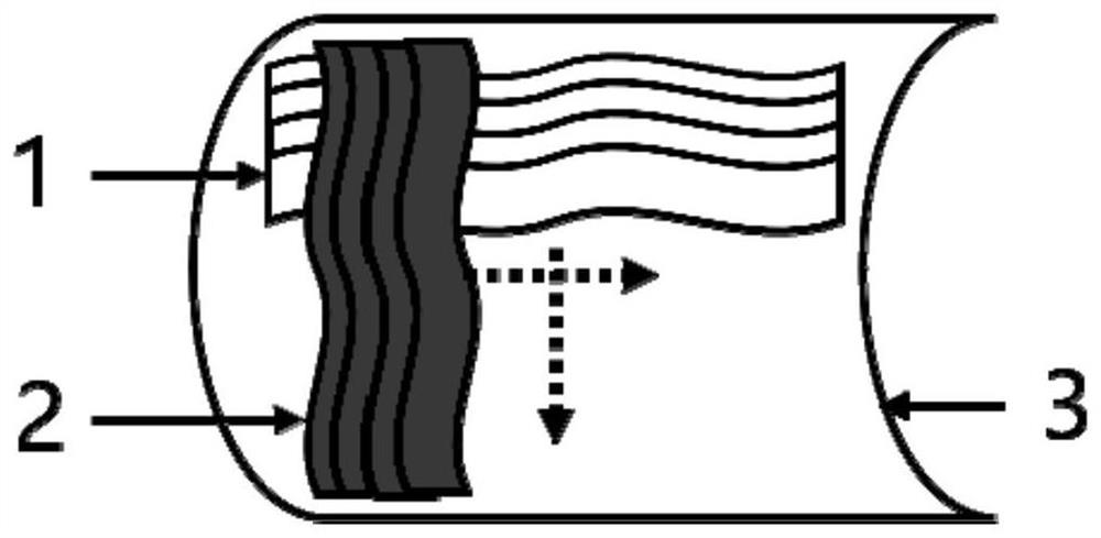
[0059] It can be understood that in this embodiment, two adjacent cladding layers adopt cladding methods with different cladding directions to form a cladding layer similar to a curved network structure. The surface of the cladding layer is flattened, so that the surface of the cladding layer is flat, avoiding cracking caused by uneven surface force when the formed parts prepared by the laser cladding technology are put into use.

[0060] Specifically, performing the flattening treatment on the surface of the cladding layer includes: performing milling, wire cutting and grinding treatment on the surface of the cladding layer according to the preset surface qualit...


PUM


Abstract

The invention belongs to the technical field of laser processing, and discloses an additive manufacturing method, equipment and device, a storage medium and a metallurgical bonding part. Comprising the following steps: dividing a to-be-formed part of a curved-surface substrate into a plurality of multi-channel and multi-layer areas to obtain the number of cladding channels and the number of cladding layers; according to the number of cladding channels, multiple cladding channels are carried out on the curved-surface substrate, a first cladding layer is formed, the cladding directions of all the cladding channels of all the cladding layers are consistent, and all the cladding channels move in a curve or broken line mode; according to the number of cladding channels, multiple cladding is conducted on the substrate formed by the (2a-1) th cladding layer, a (2a) th cladding layer is formed, and the cladding direction of the (2a-1) th cladding layer is different from that of the (2a-1) th cladding layer; and the steps are repeated until cladding of the multiple cladding layers is completed. According to the invention, the cladding directions of two adjacent layers are different, so that the stress distribution states are different, the stress can be counteracted mutually, the problems that a prepared forming part is extremely easy to damage and lose efficacy, and the torsion resistance and the bending resistance are poor are solved, and the overall performance of a metallurgical bonding part is improved.

Description

technical field [0001] The present invention relates to the technical field of laser processing, in particular to an additive manufacturing method, equipment, device, storage medium and metallurgical joint. Background technique [0002] Laser cladding is a typical additive manufacturing technique that deposits a coating of material on a substrate. It utilizes minimal and controllable heat input to create a metallurgical bond between the cladding layer and the matrix with low dilution and negligible deformation. However, in the process of laser cladding, the heating and cooling speed is extremely fast, the quality of the cladding layer is difficult to guarantee, and it is unstable; due to the difference in temperature gradient and thermal expansion coefficient between the cladding layer and the base material, the A variety of defects are generated in the laser cladding technology, which leads to the formation of parts prepared by laser cladding technology, which is extremely...

Claims


Application Information

Patent Timeline
Patent Type & Authority Applications(China)
IPC IPC(8): B22F10/28B22F12/00B22F10/366B22F10/364B22F10/85B33Y10/00B33Y30/00B33Y80/00
CPCB22F10/28B22F12/00B22F10/366B22F10/364B22F10/85B33Y10/00B33Y30/00B33Y80/00
Inventor 李晖蔡敏徐召
Owner WUHAN POLYTECHNIC UNIVERSITY
Why Eureka
Try Eureka