Supercharge Your Innovation With Domain-Expert AI Agents!

Wire clamping device and dimming actuator

A clamping device and wire technology, which is applied in the direction of workpiece clamping devices, manufacturing tools, etc., can solve the problems of reducing test efficiency and inconvenient fixing of wires, and achieve the effect of avoiding wire falling off, stably fixing, and ensuring test efficiency

Pending Publication Date: 2022-07-15
昆山致乐和电子有限公司
View PDF0 Cites 0 Cited by
  • Summary
  • Abstract
  • Description
  • Claims
  • Application Information

AI Technical Summary

Problems solved by technology

[0004] The purpose of the present invention is to provide a wire clamping device and a dimming actuator to solve the problem of reducing test efficiency caused by inconvenient fixing of wires

Method used


Image

  • Wire clamping device and dimming actuator
  • Wire clamping device and dimming actuator
  • Wire clamping device and dimming actuator

Examples


Embodiment 1

[0043] In the prior art, when the dimming actuator is connected to the external wire for testing, it needs to be pre-fixed or directly fixed by screwing the screw. After the test fails, the screw needs to be screwed again. It is easy to fix the wire, which reduces the test efficiency.

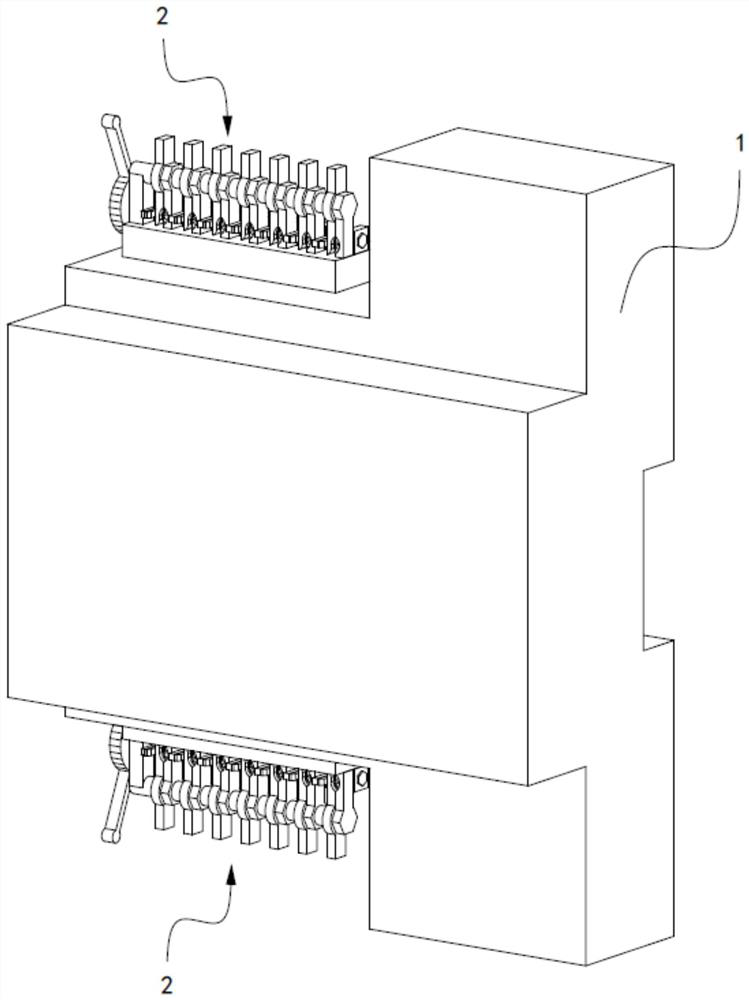
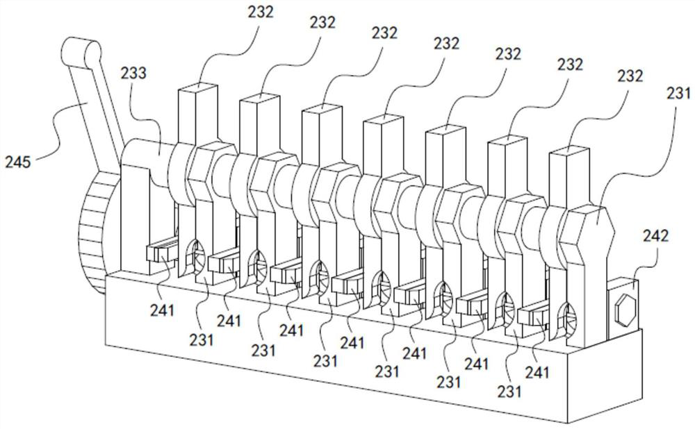
[0044] In order to solve the above problem, this embodiment provides a dimming actuator, such as Figure 1 to Figure 5 As shown, the dimming actuator 1 includes a wire clamping device 2, which can connect the externally inserted wire to the conductive terminal 21, and the wire clamping device 2 also includes a restraining mechanism 22, a positioning mechanism 23 and an actuating mechanism 23. Section 24, the restraint mechanism 22 is configured to restrain the wire inserted in the restraint mechanism 22, the restraint mechanism 22 is arranged in the restraint position, and the restraint position is selected so that the core of the exposed wire touches the conductive terminal 21, and the positio...

Embodiment 2

[0053] The difference between this embodiment and the first embodiment is that the structure of the actuating part 24 is different.

[0054] Since the handwheel 245 in the first embodiment moves together with the sliding rod 243 during the rotation process, if the dimming actuator needs to replace part of the wires, the wire clamping device 2 of the first embodiment cannot be released corresponding wire.

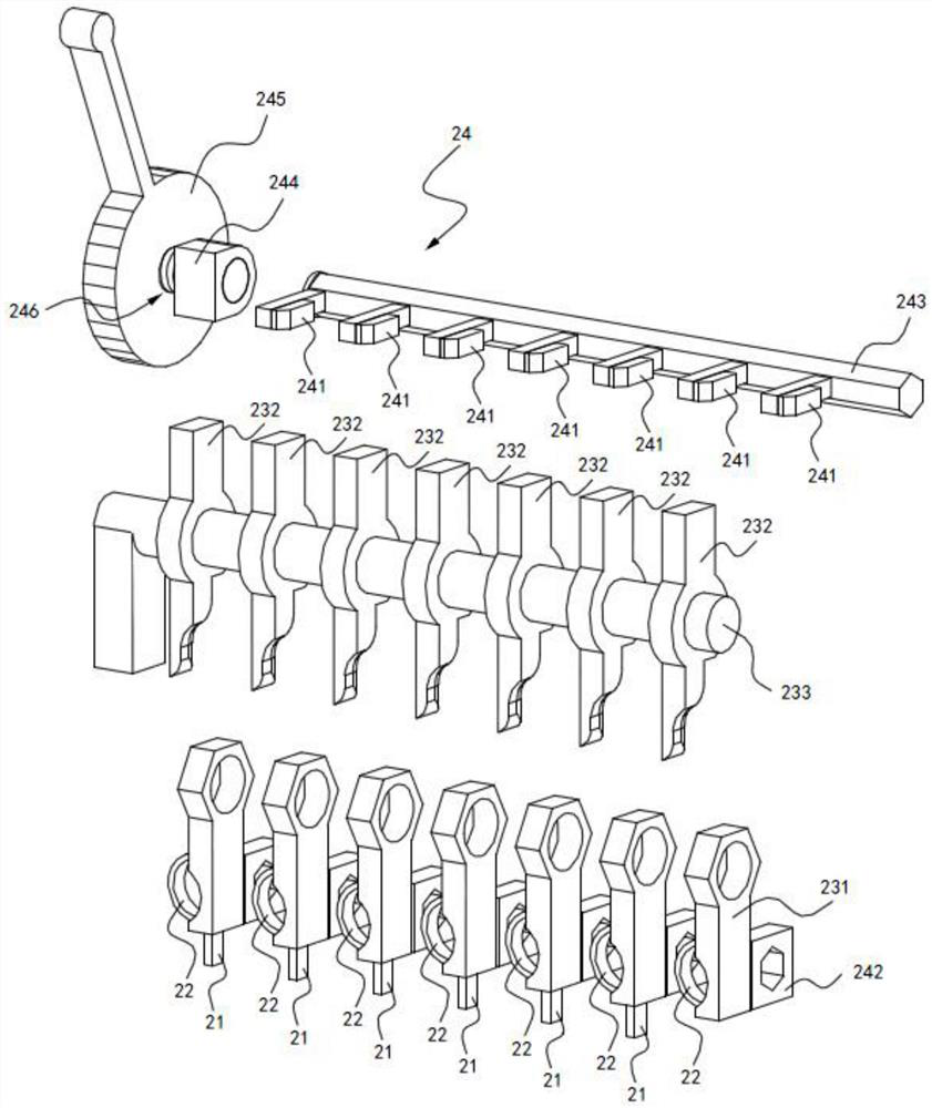
[0055] In order to solve the above problems, such as Image 6 and Figure 7 As shown, in this embodiment, the second positioning member 232 includes a base block 2322 and a positioning block 2323, the second connecting hole 2321 is provided on the base block 2322, and the base block 2322 is further provided with a diameter along the first rotating shaft 233. To the third connecting hole penetrating through the base block 2322, the second rotating shaft 246 passes through the third connecting hole and is exposed to the base block 2322. The positioning block 2323 is connecte...


PUM


Abstract

The invention belongs to the technical field of power supply equipment, and discloses a wire clamping device, which comprises a conductive terminal, a binding mechanism, a positioning mechanism and an actuating part, and is characterized in that the binding mechanism is configured to bind a wire inserted into the binding mechanism and is arranged at a binding position; the binding position is selected to be suitable for a wire core exposed out of the wire to touch the conductive terminal, the positioning mechanism has a first working state for avoiding the wire located outside to be inserted into the binding mechanism and a second working state for pulling the wire core located outside to abut against the conductive terminal, and the positioning mechanism and the binding mechanism are sequentially arranged in the inserting direction of the wire. The positioning mechanism is connected to the output end of the actuating part, and the actuating part can actuate the positioning mechanism in the second working state and enable the positioning mechanism to clamp the wire core and the conductive terminal. On the other hand, the invention provides a dimming actuator. According to the invention, the wire can be stably fixed, the wire can be prevented from falling off when the acting part releases the wire, and the test efficiency is ensured.

Description

technical field [0001] The invention relates to the technical field of power control equipment, and in particular, to a wire clamping device and a dimming actuator. Background technique [0002] Actuator is an indispensable and important part of automatic control system. Its function is to receive the control signal sent by the controller and change the size of the controlled medium, thereby maintaining the controlled variable at the required value or within a certain range. When the conventional dimming actuator is connected to the wire test, it needs to be pre-fixed or directly fixed by screwing the screw. After the test fails, the screw needs to be screwed again, and the wire is easy to fall off during the screwing process, which is inconvenient to fix the wire. Test efficiency. [0003] Therefore, it is urgent to solve the above problems. SUMMARY OF THE INVENTION [0004] The purpose of the present invention is to provide a wire clamping device and a dimming actuato...

Claims


Application Information

Patent Timeline
IPC IPC(8): B25B11/00
CPCB25B11/00
Inventor 田荣
Owner 昆山致乐和电子有限公司
Features
  • R&D
  • Intellectual Property
  • Life Sciences
  • Materials
  • Tech Scout
  • Unparalleled Data Quality
  • Higher Quality Content
  • 60% Fewer Hallucinations
Learn More