Autonomous control type hydrofoil system

A hydrofoil and controller technology, applied in the field of hydrofoil systems, can solve problems such as ship control exposure, achieve the effects of reducing ship cleaning, improving ride comfort, and avoiding human errors

Pending Publication Date: 2022-07-15
ARTEMIS TECH LTD
View PDF0 Cites 0 Cited by
  • Summary
  • Abstract
  • Description
  • Claims
  • Application Information

AI Technical Summary

Problems solved by technology

However, all controls are manual, for example using control systems with mechanical lever arms, and the fins require human intervention, which inherently requires extensive experience from the user, exposing the ship controls to human error

Method used


Image

  • Autonomous control type hydrofoil system
  • Autonomous control type hydrofoil system
  • Autonomous control type hydrofoil system

Examples


Embodiment Construction

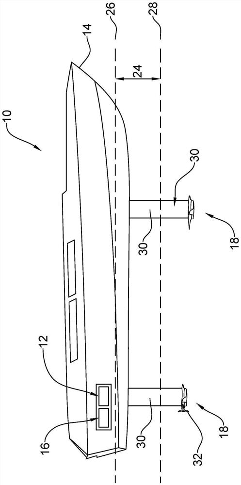
[0048] figure 1 A watercraft in the form of a monohull 10 provided with an embodiment of a hydrofoil system according to a first embodiment of the invention is shown. The hydrofoil system includes a controller 12 located within the hull 14 of the vessel 10 .

[0049] A battery system 16 is located near the controller 10 and is in electrical communication with the controller 10 . exist figure 1 In the embodiment of the present invention, the battery system 16 includes a power electronic control unit (PECU).

[0050] The hydrofoils 18 are located below the floating waterline, on the outer surface of the hull. The hydrofoil 18 includes a plurality of adjustment members 19 operable to change the lift characteristics of the vessel 10 during travel. Each adjustment member includes a tab 20 and an associated actuator 22 . The actuator 22 may be electric or hydraulic and may be integrated within the hydrofoil 18 (eg figure 1 shown) or may be located within the vessel 10 itself, ...


PUM


Abstract

The invention relates to a hydrofoil system for a water vessel (10), the hydrofoil system comprising: a controller (12); a hydrofoil (18) for engagement with the water vessel, the hydrofoil comprising a plurality of adjustment members (19) operable to vary a lift characteristic of the water vessel; a propeller (32); an engine (42) and a gearbox (44) located proximate the hydrofoil and operably / mechanically associated with the propeller; a plurality of sensors in electrical communication with the controller, each sensor configured to monitor a sailing parameter of the water vessel and generate measured sailing parameter data; wherein the controller is in communication with the adjustment member, the engine, and the sensor, and wherein the controller is configured to receive measured sailing parameter data from the sensor and control operation of the engine and a position of the adjustment member in accordance with the received measured sailing parameter data. A water vessel comprising the hydrofoil system is also provided.

Description

technical field [0001] The present invention relates to an autonomously controlled electric hydrofoil system for use with yachts, sailboats and ships. In particular, the present invention relates to such a hydrofoil system incorporating a high power density electric engine. Background technique [0002] A sailing hydrofoil is a wing-like structure installed under the hull of a vessel, such as a yacht, that provides speed advantages over more traditional vessel designs. Sailing hydrofoils work using their wing-like attachments. Just like wings on an airplane provide lift, hydrofoils in water can do the same thing. The main difference is that hydrofoils don't need to be as large as airplane wings because water is much denser than air. As the speed of the boat increases, the hydrofoil lifts most of the hull, or even the entire hull, out of the water, greatly reducing the wetted area, resulting in a reduction in drag and an increase in speed, as if a ship cut through water. ...

Claims


Application Information

Patent Timeline
Patent Type & Authority Applications(China)
IPC IPC(8): B63B1/24B63B1/28
CPCB63B1/246B63B1/286B63B79/40B63B79/10B63H21/21
Inventor I·珀西R·英戈夫
Owner ARTEMIS TECH LTD
Why Eureka
Try Eureka