Drive axle clamp for automobile drum brake bench test
A drum brake, bench test technology, used in manufacturing tools, vehicle testing, machine/structural component testing, etc., can solve problems such as unsatisfactory test results, changes in system rigidity, and difficulty in restoring the force form of the brakes. To achieve the desired effect of the test results
- Summary
- Abstract
- Description
- Claims
- Application Information
AI Technical Summary
Problems solved by technology
Method used
Image

Examples
Embodiment 1
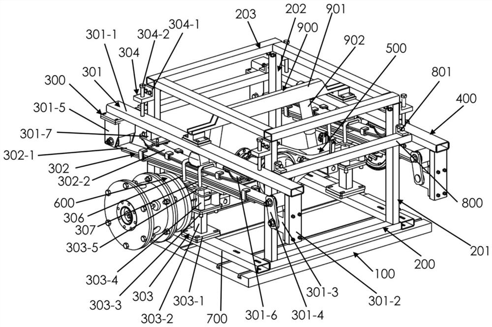
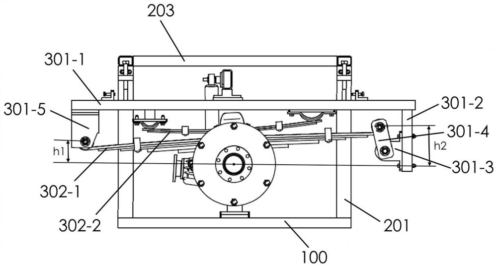
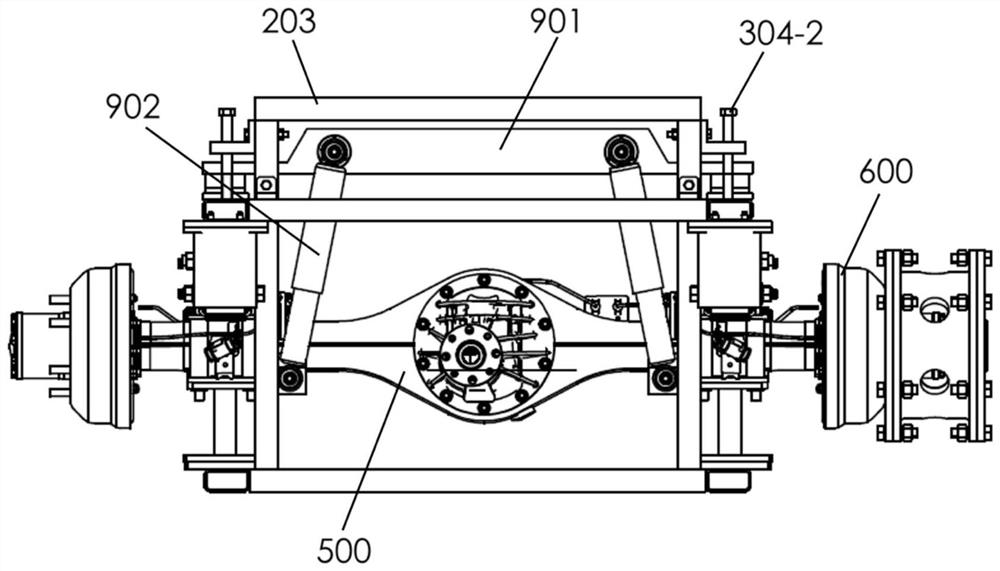
[0032] figure 1 is a schematic perspective view of a drive axle fixture for an automobile drum brake bench test according to an embodiment of the present application; figure 2 Yes figure 1 Front view of the transaxle fixture for bench testing of automotive drum brakes shown; image 3 Yes figure 1 Side view of the transaxle jig for the automotive drum brake bench test shown. like figure 1 , figure 2 and image 3 As shown, in a specific embodiment, a transaxle fixture for an automobile drum brake bench test can generally include a sliding table base 100, a support frame 200, a first force balance assembly 300, and a second force balance assembly 400, transaxle 500, and drum brake 600 for the test.
[0033] In detail, the sliding table base 100 is arranged horizontally and can be fixed to the ground by means of expansion bolts. The support frame 200 is installed on the upper part of the sliding table base 100 by bolts or welding, and is used to support the first force b...
Embodiment 2
[0037] like figure 1 As shown, in one embodiment, the features defined in any of the above embodiments are included and further and optionally. The support frame 200 may generally include a first support frame 201 , a second support frame 202 and a top frame 203 .
[0038] In detail, the first support frame 201 is vertically arranged and installed on the first side of the slide base 100 by bolts or welding, and the second support frame 202 is vertically arranged and installed on the second side of the slide base 100 by bolts or welding , and is disposed opposite to the first side support frame 201 to achieve the technical effect of support. The top frame 203 is welded or bolted to the tops of the first support frame 201 and the second support frame 202 to increase the stability of the first support frame 201 and the second support frame 202 .
[0039] Further, the first support frame 201, the second support frame 202 and the top frame 203 are all rectangular bodies to improv...
Embodiment 3
[0042] like figure 1 As shown, in one embodiment, the features defined in any of the above embodiments are included and further and optionally. The first force balance assembly 300 and the second force balance assembly 400 have the same structure, and the first force balance assembly 300 may generally include a loading frame 301 , a leaf spring assembly 302 and a base 303 .
[0043] In detail, the loading frame 301 is respectively connected with one side of the first support frame 201 and the second support frame 202 through the connecting assembly 304 , the leaf spring assembly 302 is located inside the loading frame 301 and is movably connected with the loading frame 301 , the base 303 The lower part of the base 303 is welded or bolted to the upper part of the sliding table base 100, and is located below the leaf spring assembly 302. The upper part of the base 303 is connected to the leaf spring assembly 302 for supporting and fixing the drive axle 500 and for connecting the...
PUM
 Abstract
Description
Claims
Application Information
 - R&D
- Intellectual Property
- Life Sciences
- Materials
- Tech Scout
- Unparalleled Data Quality
- Higher Quality Content
- 60% Fewer Hallucinations
Browse by: Latest US Patents, China's latest patents, Technical Efficacy Thesaurus, Application Domain, Technology Topic, Popular Technical Reports.
© 2025 PatSnap. All rights reserved.Legal|Privacy policy|Modern Slavery Act Transparency Statement|Sitemap|About US| Contact US: help@patsnap.com