
Anti-falling infusion hanger

An anti-dropping and hanger technology is applied in the field of infusion hangers, which can solve the problems of smashed patients and accidental detachment of the infusion stand, and achieves the effects of low cost, prevention of accidental shedding, and improved safety.

Inactive Publication Date: 2022-07-22
ANQING MUNICIPAL HOSPITAL
View PDF0 Cites 0 Cited by
  • Summary
  • Abstract
  • Description
  • Claims
  • Application Information

AI Technical Summary

Problems solved by technology

In order to achieve the above functions, in the traditional infusion stand, a closed hanging nose is generally hung downward on the slider, and a partially opened semi-circular hook is connected to the top of the rod on the infusion hanger. Because there is an opening at the interface, the infusion stand often appears Accidental detachment, resulting in adverse events of crushing injury to the patient

Method used


Image

  • Anti-falling infusion hanger
  • Anti-falling infusion hanger
  • Anti-falling infusion hanger

Examples


Embodiment 1

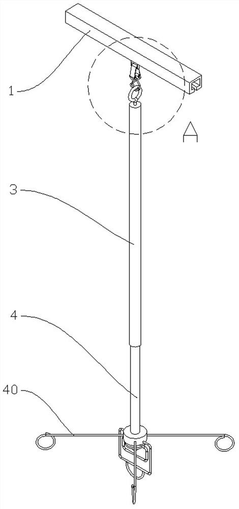
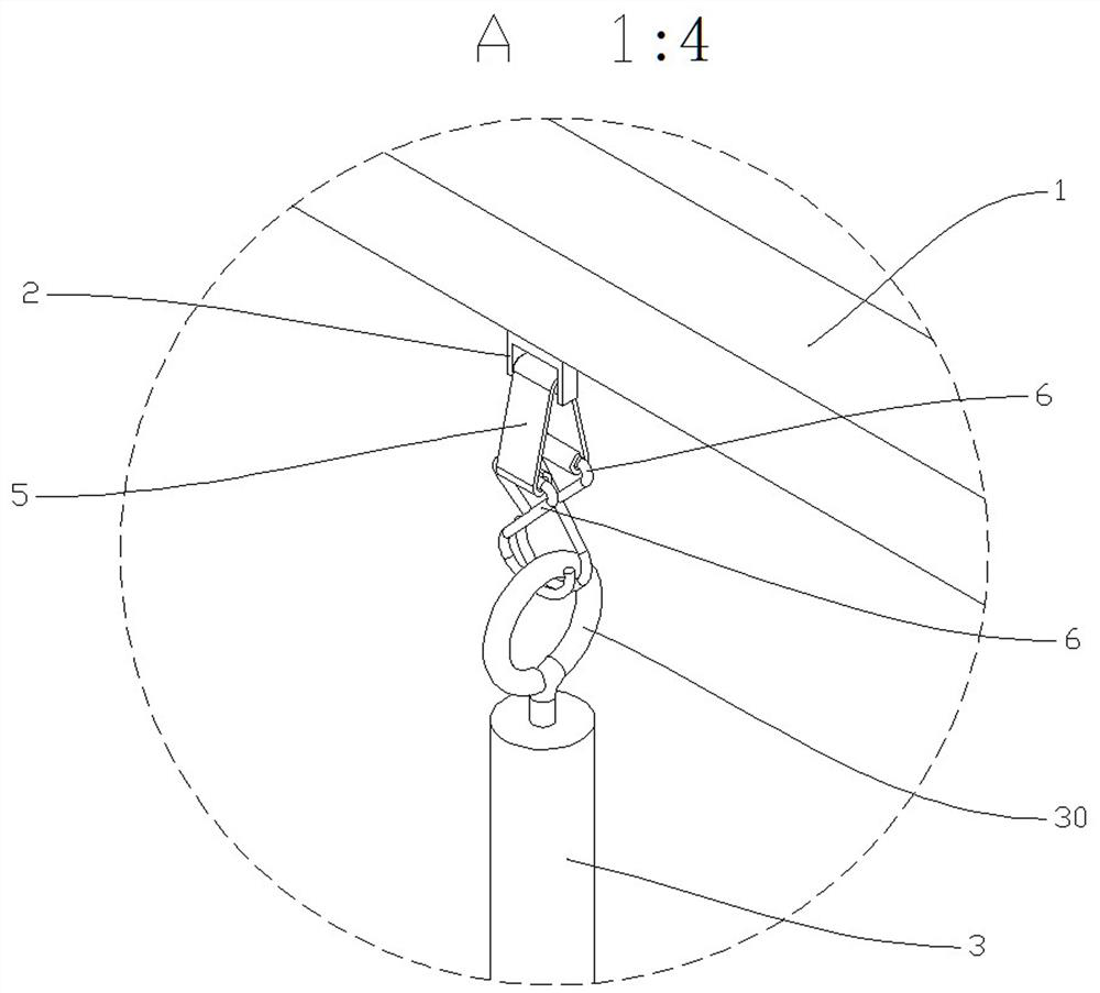
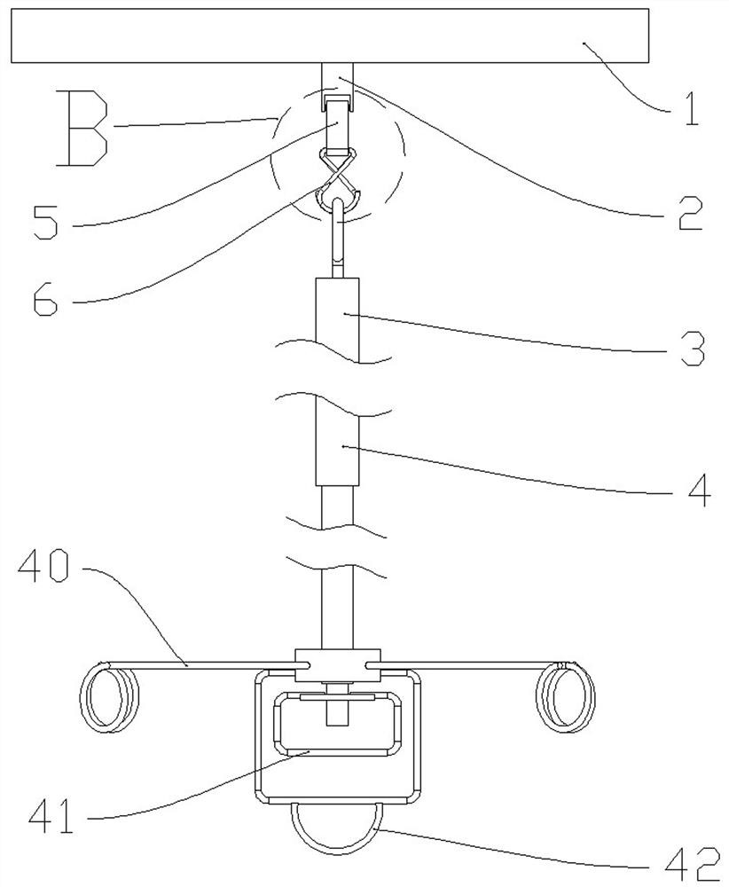
[0026] like figure 1 , figure 2 , image 3 , Figure 4 , Figure 5 It can be seen that the anti-falling infusion hanger of the present invention includes a guide rail 1 with an opening on the lower end surface, a slider 2 is movably arranged in the guide rail 1, and an upper rod 3 and a lower rod 4 arranged coaxially. There are several hanging bottle hooks 40 evenly distributed on the upper part 4 along the circumferential direction, and also includes a sliding block hook connecting body 5 formed by bending a steel plate, and the sliding block hook connecting body 5 is bent at the middle end so that the cross section is an arc. The two free ends of the slider hook connecting body 5 are symmetrically bent into two cylinders 50; it also includes two hooks 6 formed by bending a wire with a circular cross-section.

[0027] The hook bars of the two hooks 6 are respectively movably arranged in a cylinder 50, and the hook bars are coaxially arranged with the cylinder 50; the low...

Embodiment 2

[0038] like Figure 7 It can be seen that in this embodiment, the structure of the slider hook connecting body 5 is different, and the connection manner of the slider hook connecting body 5 and the slider 2 is also different.

[0039] In this embodiment, the slider hook connecting body 5 is bent at its middle end into a joint portion with a circular arc cross section, and the two free ends of the slider hook connecting body 5 are symmetrically bent into two circles Cylinder 50; the difference is that: the two transition sections between the two cylinders 50 and the joint part are parallel to each other, and the distance between the two transition sections is smaller than the diameter of the joint part.

[0040] In this embodiment, the lower end of the slider 2 is symmetrically provided with left and right pin holes, and a slider hook connecting bolt 7 is arranged between the left and right pin holes. The arc-shaped joint part is movably sleeved on the slider hook connecting b...


PUM


Abstract

The invention discloses an anti-falling infusion hanger which comprises a guide rail, a sliding block, an upper rod, a lower rod and a sliding block hook connecting body, the upper rod and the lower rod are coaxially arranged, a plurality of infusion bottle hooks are evenly distributed on the lower rod in the circumferential direction, and the sliding block hook connecting body is formed by bending a steel plate. The middle end of the sliding block hook connecting body is bent to form a combination part with an arc-shaped cross section, and two free ends of the sliding block hook connecting body are symmetrically bent to form two cylinders; the two hooks are formed by bending a wire rod with a circular cross section; the sliding block is movably connected with the sliding block hook connecting body; the hook cross rods of the two hooks are respectively and movably arranged in a cylinder, and the hook cross rods and the cylinders are coaxially arranged; the free ends of the lower parts of the two hooks are bilaterally symmetrical; an upper rod lantern ring is arranged at the top of the upper rod; and the upper rod lantern ring is hung on the arc-shaped hooks of the two hooks in a sleeving manner. The upper rod and accessories thereof can be prevented from accidentally falling off from the guide rail, and high safety is achieved.

Description

technical field [0001] The invention relates to medical equipment, in particular to an infusion hanger. Background technique [0002] The infusion rack is an accessory required for intravenous injection, which is mainly used for hanging infusion bags or infusion bottles. [0003] In the prior art, the roof of the ward is provided with a guide rail and a slider, and the infusion hanger is movably connected with the slider. The infusion hanger includes an upper rod and a lower rod, and a relative distance locking device is arranged between the two to adjust the height of the infusion. [0004] During the infusion process, the patient needs to get out of bed to go to the toilet or move, so the infusion rack and the guide rail need to be detachable. In order to achieve the above functions, in the traditional infusion stand, a closed nose is generally hung downward on the slider, and a partially open semi-circular arc hook is connected to the top of the upper rod of the infusio...

Claims


Application Information

Patent Timeline
IPC IPC(8): A61M5/14
CPCA61M5/1415A61M5/1417A61M5/1413
Inventor 汪洋
Owner ANQING MUNICIPAL HOSPITAL
Learn More