Mold anti-adhesion device used after glue injection forming

An anti-adhesion and mold technology, which is applied in the field of anti-adhesion devices, can solve the problems of time-consuming cooling and achieve the effect of improving work efficiency

Pending Publication Date: 2022-07-22
伟盛扣具制品(深圳)有限公司
View PDF11 Cites 0 Cited by
  • Summary
  • Abstract
  • Description
  • Claims
  • Application Information

AI Technical Summary

Problems solved by technology

[0005] Aiming at the deficiencies of the prior art, the present invention provides an automatic cooling mold anti-adhesion device after injection molding to overcome the time-consuming cooling disadvantage of the existing anti-adhesion device

Method used


Image

  • Mold anti-adhesion device used after glue injection forming
  • Mold anti-adhesion device used after glue injection forming
  • Mold anti-adhesion device used after glue injection forming

Examples


Embodiment 1

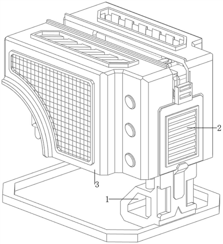
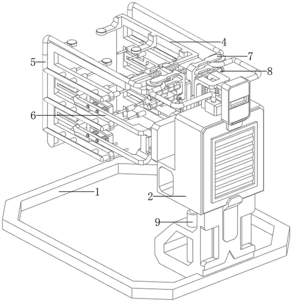
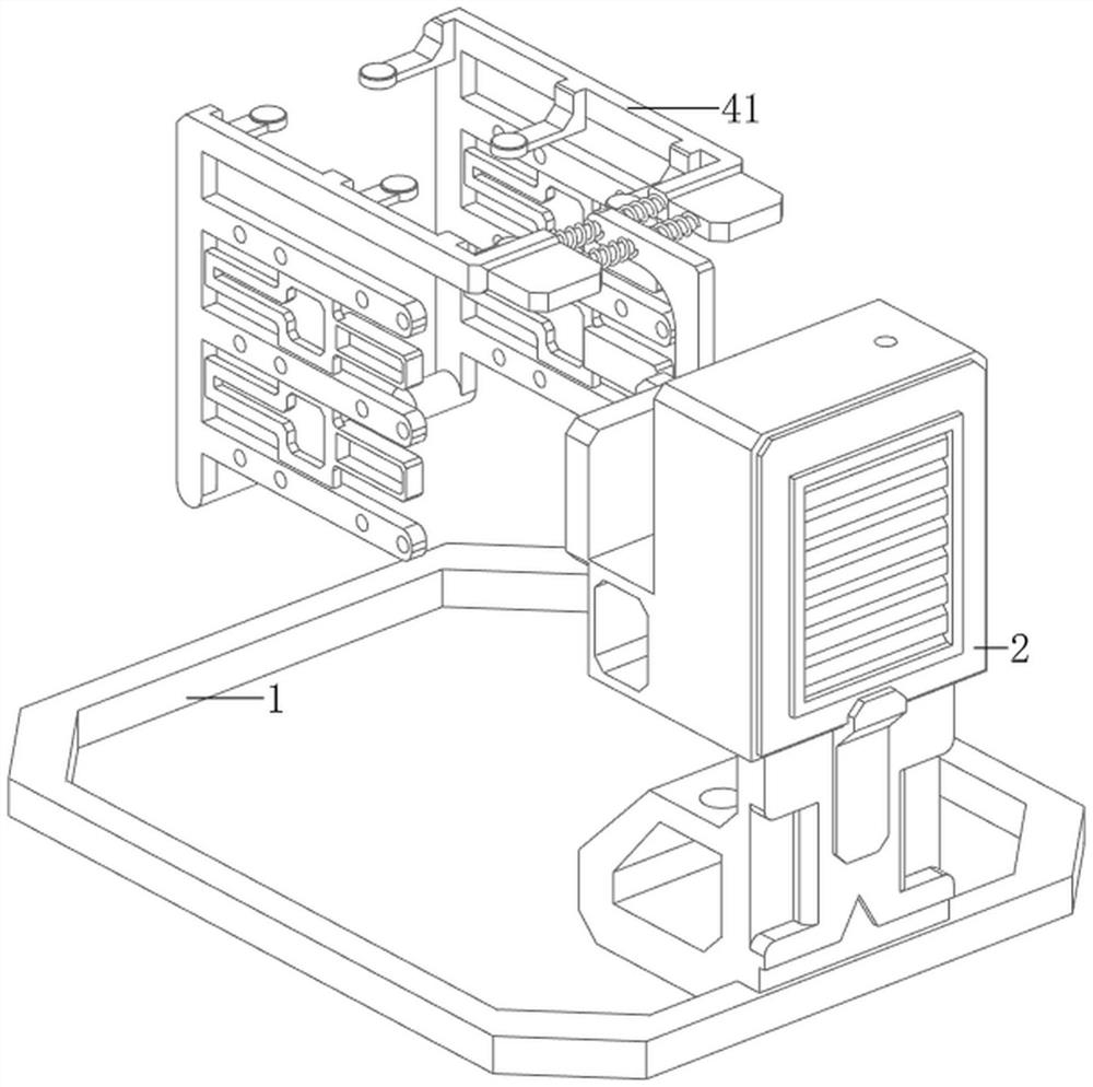
[0072] A mold anti-adhesion device after injection molding, now refer to Figure 1-2 , including a base frame 1, a mounting plate frame 2, a protective casing 3, a connection mechanism 4 and an anti-adhesion mechanism 5, a mounting plate frame 2 is placed on the front side of the upper part of the base frame 1, and a connecting mechanism 4 is installed on the mounting plate frame 2. A protective casing 3 is welded on the left and right sides of the plate frame 2 , and an anti-adhesion mechanism 5 is arranged between the mounting plate frame 2 , the protective casing 3 and the connecting mechanism 4 .

[0073] Reference now figure 2 , image 3 , Figure 4 , Figure 5 , Image 6 , Figure 7 , Figure 9 , Figure 10 and Figure 11 , the connecting mechanism 4 includes a connecting frame 41, a first sliding rod 42 and a first spring 43, two first sliding rods 42 are welded on the left and right sides of the upper part of the rear side of the mounting plate frame 2, and th...

Embodiment 2

[0077] On the basis of Example 1, now refer to figure 2 , Figure 9 , Figure 10 , Figure 11 and Figure 12 , and also includes an ejection mechanism 6, the ejection mechanism 6 includes a first moving frame 61, a thimble 62, a first telescopic rod 63, a second spring 64, a second sliding rod 65 and a third spring 66, the mounting plate frame 2 Two first telescopic rods 63 are welded to the left and right rear sides, and there are four first telescopic rods 63. A first moving frame 61 is connected between the two first telescopic rods 63 on the same side. The first moving frame A second spring 64 is connected between the upper and lower sides of the front side and the first telescopic rod 63 on the same side. There are four second springs 64. The upper and lower sides of the first moving frame 61 are provided with ejector pins 62 on the rear side. There are two second sliding rods 65 on the upper and lower sides of the connecting frame 41. The second sliding rods 65 are ...


PUM


Abstract

The invention relates to an anti-adhesion device, in particular to a mold anti-adhesion device used after glue injection forming. The invention provides an automatic-cooling mold anti-adhesion device used after glue injection forming. The invention discloses a mold anti-adhesion device used after glue injection forming. The mold anti-adhesion device comprises a bottom frame, a mounting plate frame, a protective shell, a connecting mechanism and an anti-adhesion mechanism, a mounting plate frame is placed on the front side of the upper portion of the bottom frame, protective shells are arranged on the left side and the right side of the mounting plate frame, a connecting mechanism is arranged on the mounting plate frame, and anti-adhesion mechanisms are arranged among the mounting plate frame, the protective shells and the connecting mechanism. The air blower is started by people, so that airflow flows into the air distribution box through the air guide pipe, then the airflow flows into the mold through the air guide pipe and the spray needle, the effect of accelerating cooling is achieved, and the working efficiency is improved.

Description

technical field [0001] The invention relates to an anti-adhesion device, in particular to an anti-adhesion device for a mold after injection molding. Background technique [0002] When people produce products through molds, it often occurs that the molds and the formed products are stuck together, so that people cannot easily take out the products from the molds. Therefore, it is necessary to design an anti-adhesion device. [0003] Patent application: CN209718383U, the publication date is 20191203, which discloses a slanted top anti-adhesion thimble device for molds. By including a top plate, a first spring and a template, the top plate is provided with a chute, and the interior of the chute is provided with There is a sliding block, spring grooves are opened on both sides of the sliding block, and the first spring is located inside the spring groove, wherein a ball sleeve is connected to the side of the first spring close to the sliding groove, and the ball A ball is inst...

Claims


Application Information

Patent Timeline
Patent Type & Authority Applications(China)
IPC IPC(8): B29C45/73B29C45/40B29C45/17
CPCB29C45/7337B29C45/4005B29C45/1756
Inventor 林文证黄淑玲何胜梁黄熙龙通胜
Owner 伟盛扣具制品(深圳)有限公司
Why Eureka
Try Eureka